Plate-shaped shearing knife

Inactive Publication Date: 2003-10-21
PLANSEE TIZIT
View PDF14 Cites 5 Cited by
  • Summary
  • Abstract
  • Description
  • Claims
  • Application Information

AI Technical Summary

Benefits of technology

The purpose of the present invention is to create plate-shaped shearing knives of hard metal for shearing off allotments of liqu

Problems solved by technology

Such knives heat up far less, even at very high shearing frequencies and thus are subject to a smaller amount of wear.
It is not practical to increase the dimensions of the shearing knife indefinitely to increase the thermal absorption of the shearing knife

Method used


Image

  • Plate-shaped shearing knife
  • Plate-shaped shearing knife
  • Plate-shaped shearing knife

Examples


Example

We have:

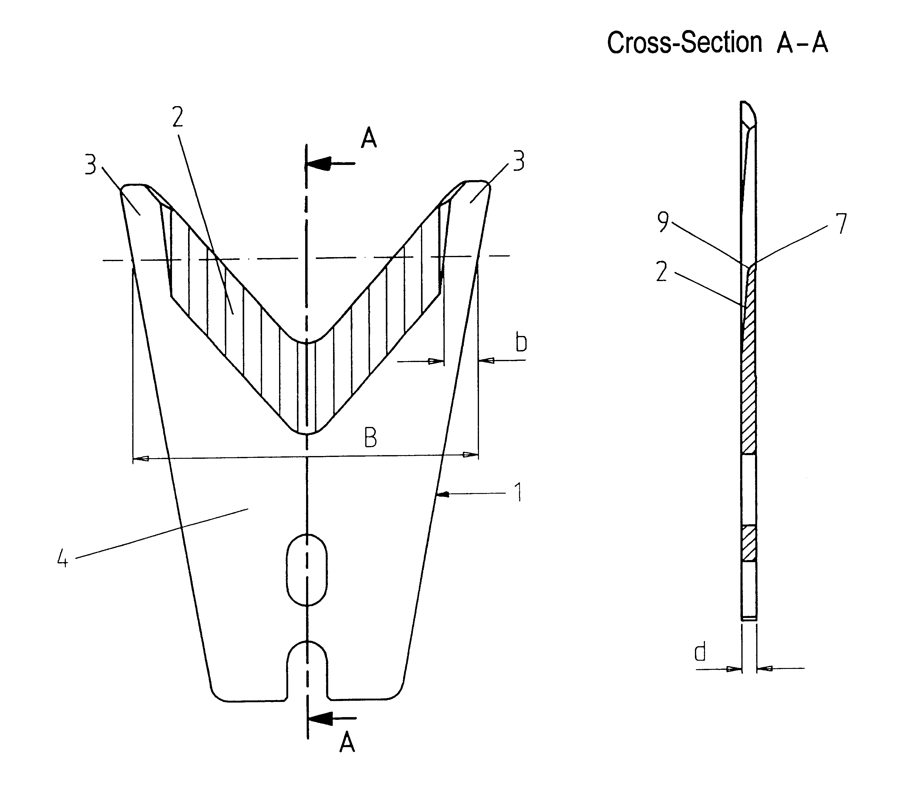
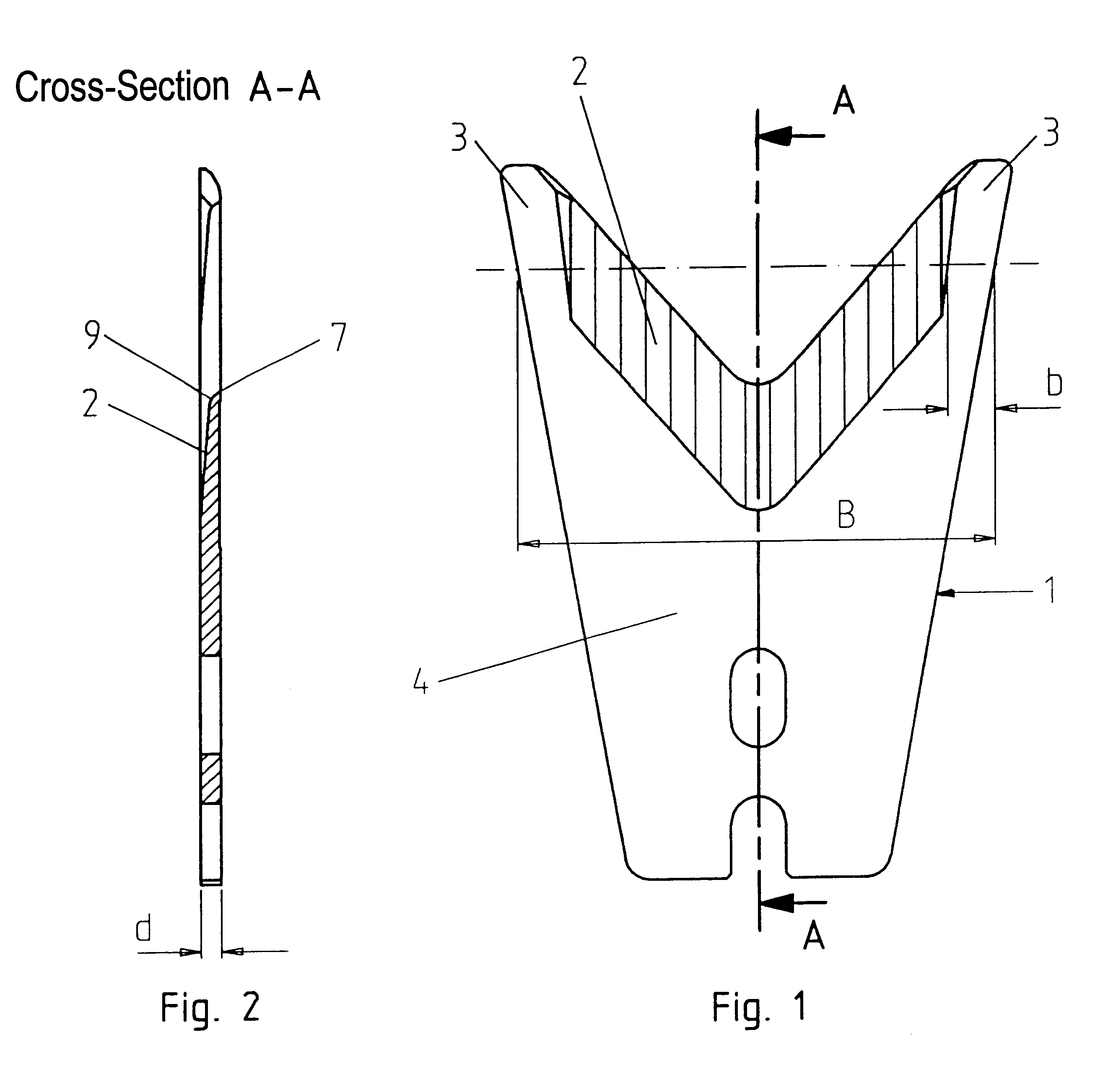
FIG. 1 A fundamental sketch of a shearing knife, according to this invention, shown in top view.

FIG. 2 The shearing knife, according to FIG. 1, showing cross section A--A.

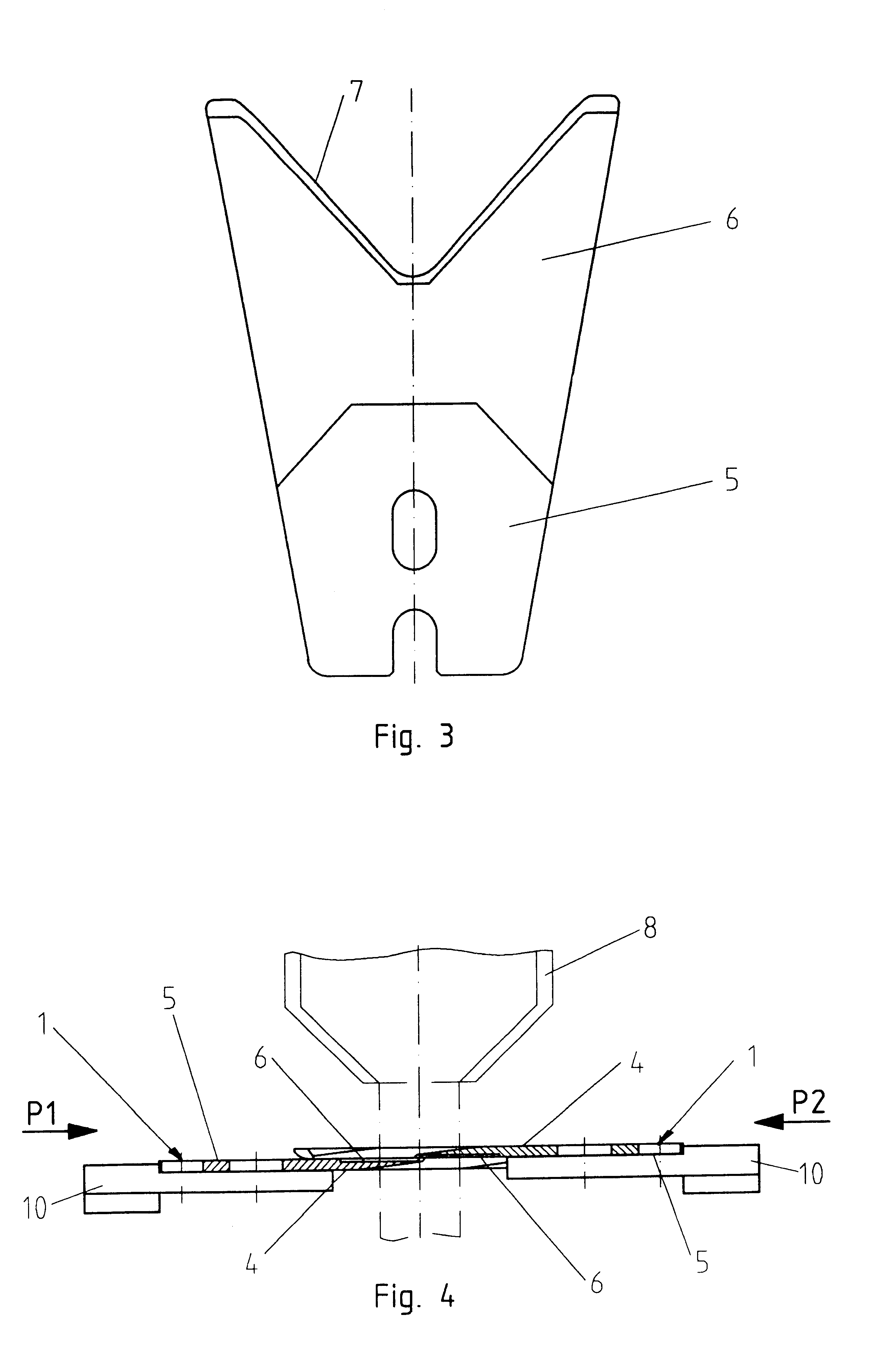
FIG. 3 The underside of the shearing knife according to FIG. 1.

FIG. 4 A fundamental sketch of a shearing device with paired working shearing knives, according to this invention, presented in a side view.

The plate-shaped shearing knife -1-, according to this invention and as represented in FIGS. 1 to 3, is made of a hard metal alloy comprising 90 wt % of tungsten carbide and 9 wt % of cobalt. The top side -4- is of flat design except for the region -2- of the cutting edge. The V-shaped cutting region -2- has a wedge-shaped cross section with respect to the plate thickness d of the shearing knife. On both sides adjoining this cutting region -2-, the shearing knife -1- has an edge region -3-, that is not wedge-shaped, and flares out.

This edge region -3- is dimensioned so that its average width b, viewed with r...


PUM

PropertyMeasurementUnit
Fractionaaaaaaaaaa
Fractionaaaaaaaaaa
Lengthaaaaaaaaaa

Abstract

A plate-shaped shearing knife is provided made of hard metal for shearing off allotments of liquid glass. The hard metal of the shearing knife has a thermal conductivity of at least 85 W/mK. Next to a V-shaped or circular-shaped cutting region -2-, there are edge regions on both sides that do not flare out wedge-like, and have an average width b which is in a range of 5% to 30% of the total width of the shearing knife B in this section.

Description

The present invention pertains to a plate-shaped shearing knife for shearing off allotments of liquid glass, the knife having a roughly V-shaped or circular-shaped cutting region and a wedge-shaped cross section with respect to its thickness.Shearing knives of this kind are used in pairs in fully-automated systems, and use opposing movements to shear off glass allotments from a stream of liquid glass from a glass reservoir, these allotments can then be processed into glass bottles, container glass, video screens, and similar products.In particular, when shearing off small allotments of glass, as occurs in the manufacture of glass bottles, container glass, or incandescent light bulbs, the shearing process takes place at a very high frequency, i.e., about 100 shearing steps per minute or more.Because of this high frequency, the shearing knives are in direct contact with the glass melt over a relatively long period of time, and this glass melt has a temperature of between about 1100.de...

Claims


Application Information

Patent Timeline
IPC IPC(8): C03B7/11C03B7/00
CPCC03B7/11Y10T83/9447
Inventor GRUBER, BERNDREINHARDT, HERMANNSCHRETTER, MICHAEL
Owner PLANSEE TIZIT
Why Eureka
Try Eureka