
Martensitic stainless steel machineability optimization

a technology of martensitic stainless steel and optimization method, which is applied in the direction of heat treatment process control, heat treatment apparatus, manufacturing tools, etc., can solve the problems of difficult to predict parts of complex shapes, changes in dimensions, and inability to perform quality heat treatment, so as to improve the machineability of such steels

Active Publication Date: 2016-10-11
SN DETUDE & DE CONSTR DE MOTEURS DAVIATION S N E C M A
View PDF8 Cites 0 Cited by
  • Summary
  • Abstract
  • Description
  • Claims
  • Application Information

AI Technical Summary

Benefits of technology

The invention aims to improve the ability to machine steels using methods that require less cutting of the insert, leading to less wear and power usage. Additionally, the surface quality of the machined steel is improved, resulting in more efficient use of the steel and reduced costs.

Problems solved by technology

This quality heat treatment cannot be performed after the machining since that would lead to changes in dimensions that are difficult to predict for parts of complex shape.
The changes in crystallographic volume that accompany such transformations therefore lead to internal stresses and, at the end of quenching (because of the low temperatures that are then reached), they limit the extent to which the stresses can be relaxed.
There then remains a residual austenite content in the steel that it has not been possible to transform.
In spite of this quality heat treatment, while workpieces are being machined, it is found at present that there is a large amount of dispersion in the machineability of batches of workpieces made of a steel that is the result of such a fabrication method.
This can lead to large variations in the amount of wear of machining inserts and in large variations in the levels of power that the machine tool needs to deliver in order to be able to machine such steel workpieces.
Consequently, the consumption of machining inserts is too high, too greatly dispersed, and unpredictable, thereby giving rise to reduced rates of throughput when machining batches of workpieces, and also to dispersion in the resulting surface states, sometimes leading to workpieces with machined surface states of poorer quality.

Method used


Image

  • Martensitic stainless steel machineability optimization
  • Martensitic stainless steel machineability optimization

Examples


Embodiment Construction

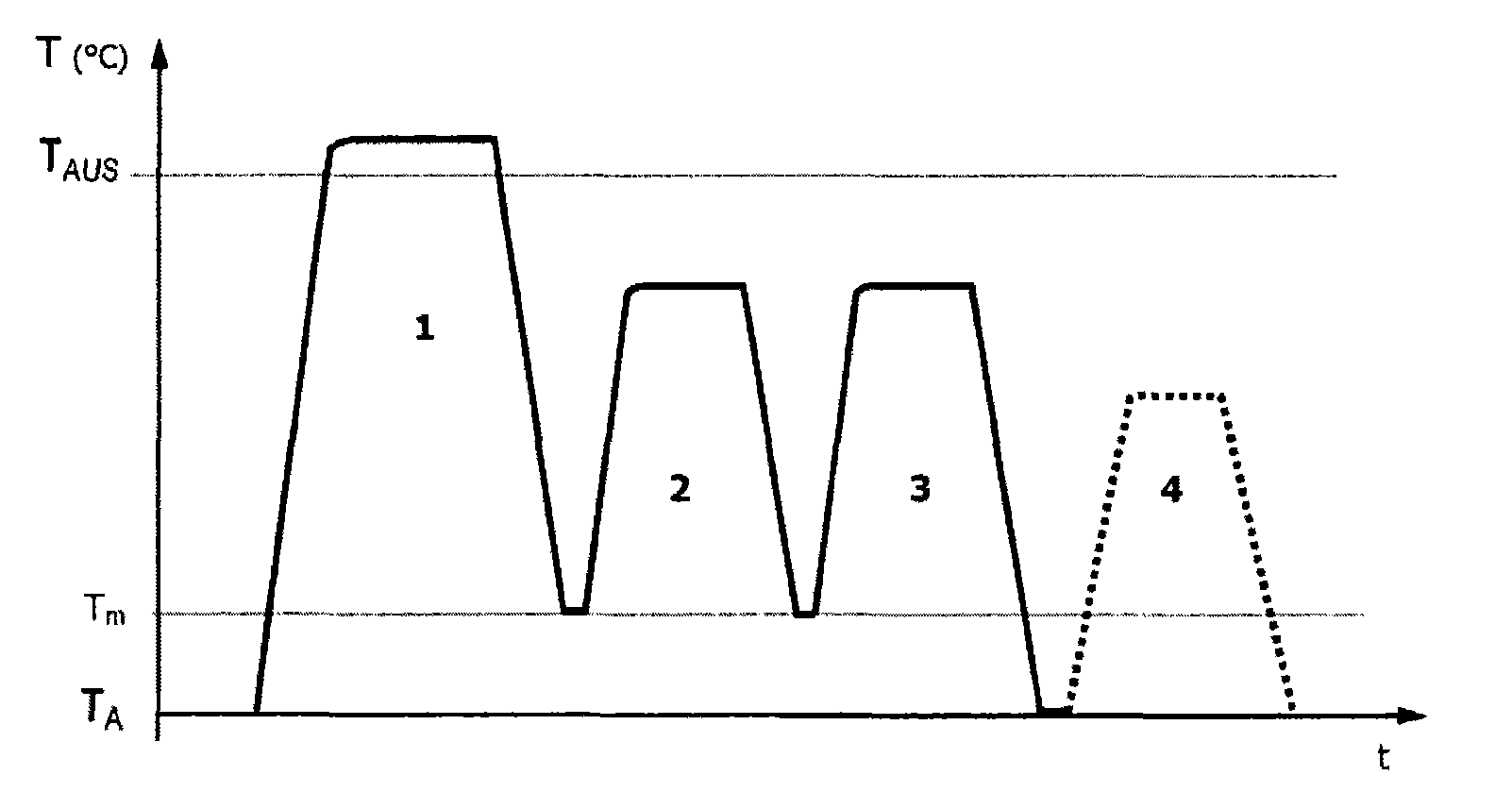
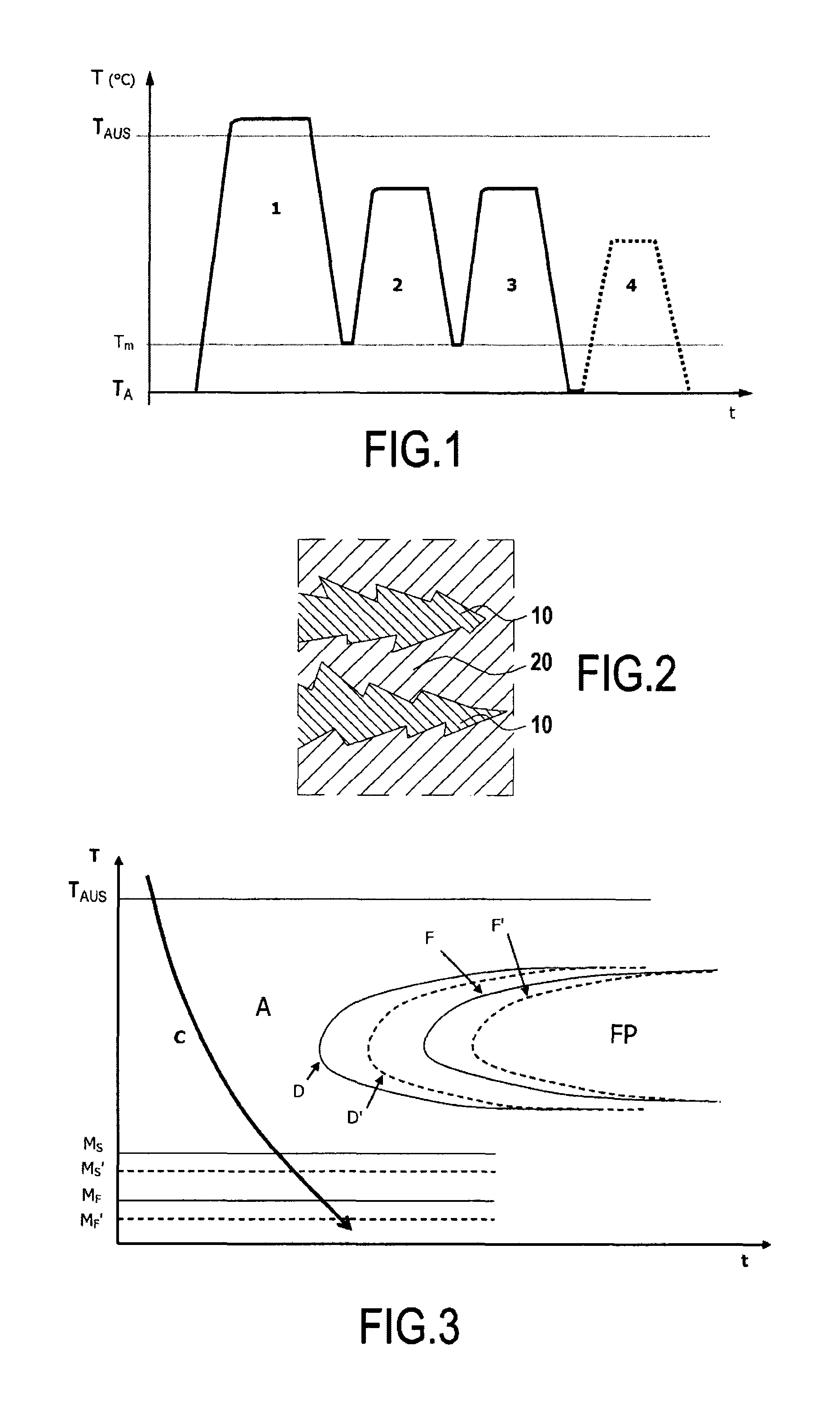
[0036]In the method of the invention, the starting material is a blank with extra thicknesses that has been subjected to a succession of thermomechanical treatments (such as forging, rolling) in order to give it a shape that is as close as possible to its final shape.

[0037]This blank is for subsequent machining in order to give it its final shape after it has been subjected to quality heat treatment.

[0038]The blank made of this steel is heated to a temperature higher than the austenizing temperature TAUS, and the blank is maintained at this temperature until the entire blank is at a temperature higher than the austenizing temperature TAUS (austenizing the steel).

[0039]Thereafter, the steel is quenched sufficiently fast to prevent the austenite from transforming into a ferrito-perlitic structure (see FIG. 3 and the explanations given below). Thus, the major fraction of the volume of the steel blank is suitable for transforming into martensite, since austenite can be transformed into ...


PUM

PropertyMeasurementUnit
Temperatureaaaaaaaaaa

Abstract

A method of fabricating a martensitic stainless steel including: 1) heating steel to a temperature higher than austenizing temperature of the steel, then quenching the steel until a hottest portion of the steel is at a temperature less than or equal to a maximum temperature, and greater than or equal to a minimum temperature, a cooling rate being sufficiently fast for austenite not to transform into a ferrito-perlitic structure; 2) performing a first anneal followed by cooling until the hottest portion of the steel is at a temperature less than or equal to the maximum temperature and greater than or equal to the minimum temperature; 3) performing a second anneal followed by cooling to ambient temperature; and at the end of each of 1) and 2), performing: ω) as soon as temperature of the hottest portion of the steel reaches the maximum temperature, immediately heating the steel once more.

Description

BACKGROUND OF THE INVENTION[0001]1. Field of the Invention[0002]The present invention relates to a method of fabricating a martensitic stainless steel including the following heat treatment steps:[0003]1) heating the steel to a temperature higher than the austenizing temperature TAUS of the steel, then quenching the steel until the hottest portion of the steel is at a temperature less than or equal to a maximum temperature Tmax, and greater than or equal to a minimum temperature Tmin, the rate of cooling being sufficiently fast for the austenite not to transform into a ferrito-perlitic structure;[0004]2) performing a first anneal on the steel followed by cooling until the hottest portion of the steel is at a temperature less than or equal to said maximum temperature Tmax and greater than or equal to said minimum temperature Tmin; and[0005]3) performing a second anneal of the steel followed by cooling to ambient temperature TA.[0006]Ambient temperature is equal to the temperature of ...

Claims


Application Information

Patent Timeline
IPC IPC(8): C21D6/00C21D1/18C21D1/22C22C38/00C22C38/44C22C38/04C22C38/46
CPCC21D6/008C21D1/18C21D1/22C21D6/004C21D6/005C22C38/001C22C38/04C22C38/44C22C38/46C21D2211/008
Inventor CHABOT, JEAN-FRANCOIS LAURENTFERRER, LAURENTTHOISON, PASCAL CHARLES EMILE
Owner SN DETUDE & DE CONSTR DE MOTEURS DAVIATION S N E C M A
Learn More