Endoscope objective

a technology of endoscope and objective, which is applied in the field of endoscope objective, can solve the problems of complex and hence expensive manufacturing, inclination of endoscope eyepiece, and low manufacturing efficiency of endoscope objective, and achieve the effect of reducing manufacturing costs, increasing production efficiency, and increasing the number of endoscope objectiv

Inactive Publication Date: 2003-10-21
KARL STORZ GMBH & CO KG
View PDF11 Cites 53 Cited by
  • Summary
  • Abstract
  • Description
  • Claims
  • Application Information

AI Technical Summary

Problems solved by technology

Due to the use of a dual section prism unit the system with an inclined eyepiece for endoscopes, as it is known from the German Patent DE 35 37 155 A1, is complex and hence expensive to manufacture.
On account of the application of this optical flat the know...

Method used


Image

  • Endoscope objective
  • Endoscope objective

Examples


Embodiment Construction

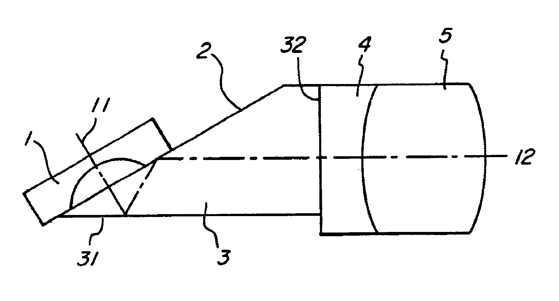
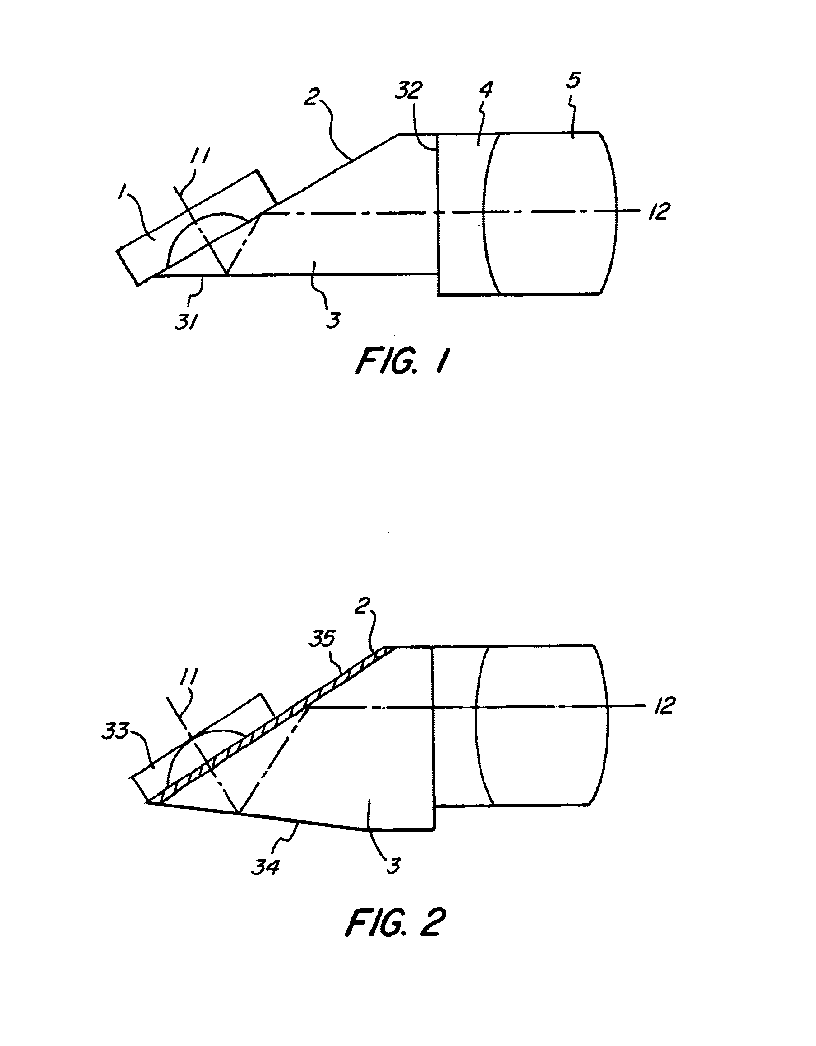
The inventive endoscope objective having a viewing direction 11 including an angle different from 0.degree., specifically 60.degree., relative to the longitudinal axis of the endoscope which is not shown in more details here, comprises a lens system consisting of lenses 1, 4 and 5 as well as further lenses if necessary, which lens system serves to image an object field into an image plane arranged orthogonally on the longitudinal axis 12 of the endoscope. This image can then be passed through an image relay system which is not illustrated here, such as a fibre bundle, a relay lens system or a video pickup, to the proximal end of the endoscope.

A prism unit 3 is provided within the lens system, in which the beam is reflected at two boundary layers, i. e. the surfaces 31 and 2, so that the beam is deflected from the desired viewing direction 11 into the longitudinal axis 12 of the endoscope in the prism unit and hence enters from the surface 32 into the joining lenses 4 and 5.

In accord...


PUM


Abstract

Endoscope objective having a viewing direction including an angle< >0° relative to the longitudinal axis of the endoscope, comprising a lens system imaging the object field into a single image plane disposed orthogonally on the longitudinal axis, and a prism unit disposed downstream of the distal window of the endoscope along the imaging path, in which the beam is reflected on two boundary surfaces such that the beam will be deflected in the prism unit from the desired viewing direction into the longitudinal axis of the endoscope, wherein a coating is applied on at least one surface on the prism unit, which comprises a thin layer having a refractive index smaller than the refractive index of the material which said prism unit is made of, so that total reflection against the layer occurs. The invention is characterized by the provision that the coating is applied to that surface of the prism unit which faces the glass cover of the endoscope.

Description

The present invention relates to an endoscope objective having a viewing direction that includes an angle of < >0.degree. relative to the longitudinal axis of the endoscope, i. e. to an endoscope objective of a so-called inclined-eyepiece endoscope.PRIOR ARTEndoscope objectives of this type are commonly known. German Patent DE 35 37 155 A1 discloses an objective comprising of a lens system which forms the image of the object field of the objective in an image plane that is disposed orthogonally on the longitudinal axis of the endoscope.That known objective comprises a lens system which forms the image of the object field of the objective in an image plane that is disposed orthogonally on the longitudinal axis of the endoscope. The image formed in the image plane is then relayed or imaged, respectively, by an image relay system into a proximal image plane. Between the lenses of the lens system a dual section prism unit is disposed in which the beam is so reflected on two bounda...

Claims


Application Information

Patent Timeline
IPC IPC(8): G02B23/24G02B13/00G02B23/00
CPCG02B23/243
Inventor LEDERER, FRANK
Owner KARL STORZ GMBH & CO KG
Why Eureka
Try Eureka