Telescope mount

a telescope and mount technology, applied in the direction of telescopes, mounts, optics, etc., can solve the problems of lack of stability, difficult to relocate, and light instruments, and achieve the effects of low thermal mass, low modulus, and cost competitiveness

Inactive Publication Date: 2003-10-28
BELCHER MICHAEL JOHN
View PDF7 Cites 6 Cited by
  • Summary
  • Abstract
  • Description
  • Claims
  • Application Information

AI Technical Summary

Benefits of technology

The ballast containers are liquid tight and adapted to contain flowable ballast material. The ballast allows the most desirable telescope mass to be obtained with any number of conventional or unconventional materials such as, wet or dry sand and or small stones, water, crushed ice and other fluids and semi-fluids and solids.
A conical ballast container is provided at one end of the fork. In the structural yoke joining the two tines of the fork is provided a substantially cylindrical ballast container. The conical container and the substantially cylindrical ballast container are separated by a drive wheel. The fork is supported on a bearing adjacent to the apex of the conical container and on rollers running on the drive wheel. The ballast containers and the wheel may be readily separated for portability.
The containers are made from high modulus lightweight composite materials. This mount, compared to the prior art, offers cost-competitive construction, together with rigidity and low thermal mass, while avoiding the need for massive foundations.
It has been found that the ballast works to improve the stability of the telescope mounting, by both favorably altering the harmonics of the mounting and reducing vibrations of the telescope. The ability to raise the mass of the telescope mount in-situ provides this improved stability by lowering the centre of gravity of the mount. The natural frequency of vibration of the stiff composite fork structure is relatively high, this natural frequency is advantageously lowered by the addition of mass. The presence of the flowable ballast material also serves to dampen vibrations in the mount, dissipating the energy within the ballast material. The high stiffness, lower natural frequency and dampening properties allow a pointing accuracy or tracking ability of the same order as the to be achieved. For example, a pointing and tracking accuracy of a few arcseconds may be readily achieved.

Problems solved by technology

Although tracking of a celestial object is more difficult with the altazimuth mount, a computer can readily handle the variable drive rates to co-ordinate the complex multiplanar motions, and telescopes with both altazimuth and equatorial mounts are often motor driven.
The support frames and foundations for these telescopes have also been correspondingly heavy making them very difficult to relocate.
These lightweight instruments however, lack stability and are adversely affected by ground vibration, wind disturbance and operational vibration.
As well as having drawbacks for ordinary viewing, this lack of stability reduces their capacity for use with sensitive auxiliary instrumentation, particularly when operating at higher magnifications.

Method used


Image

  • Telescope mount
  • Telescope mount
  • Telescope mount

Examples


Embodiment Construction

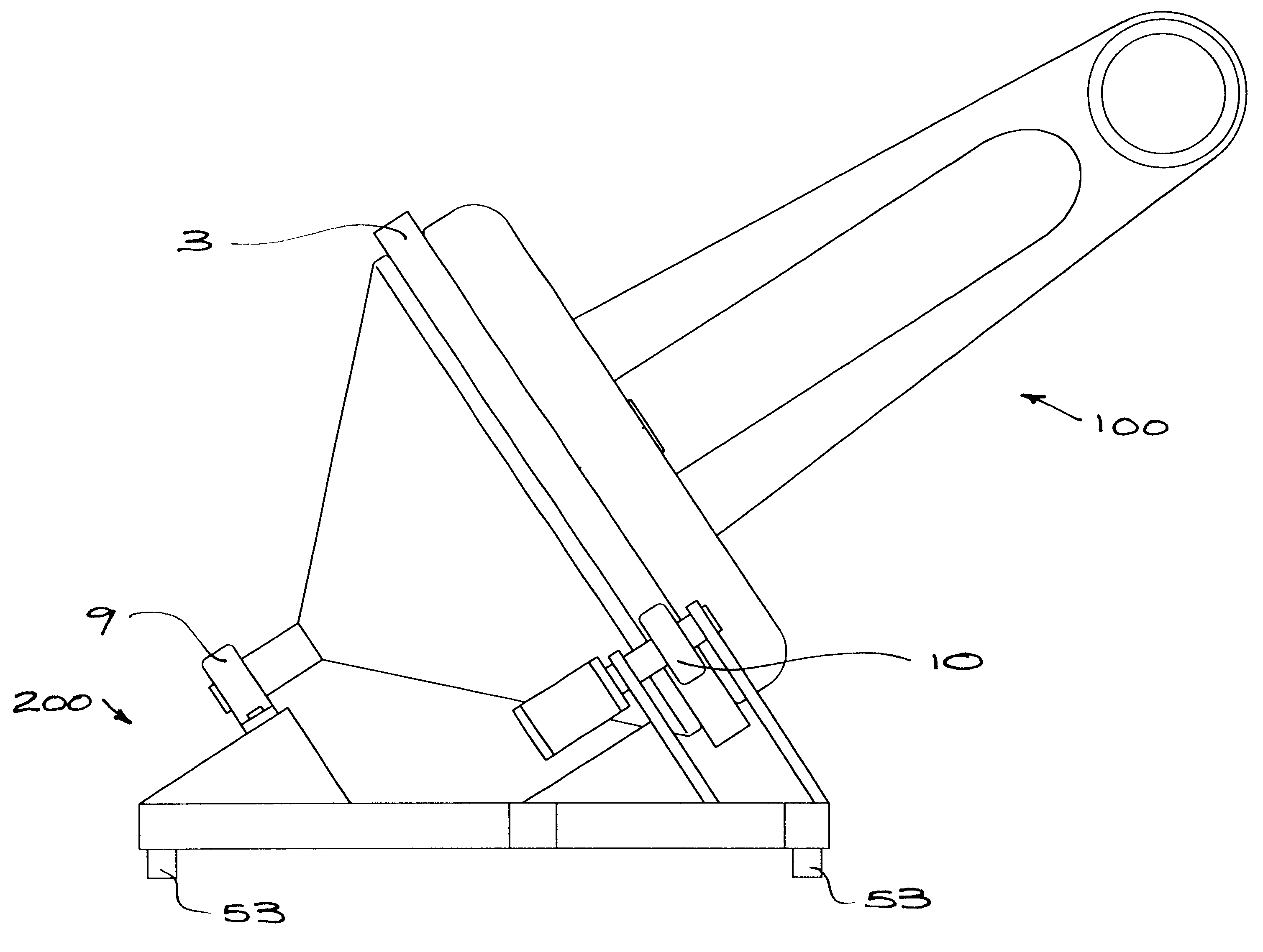
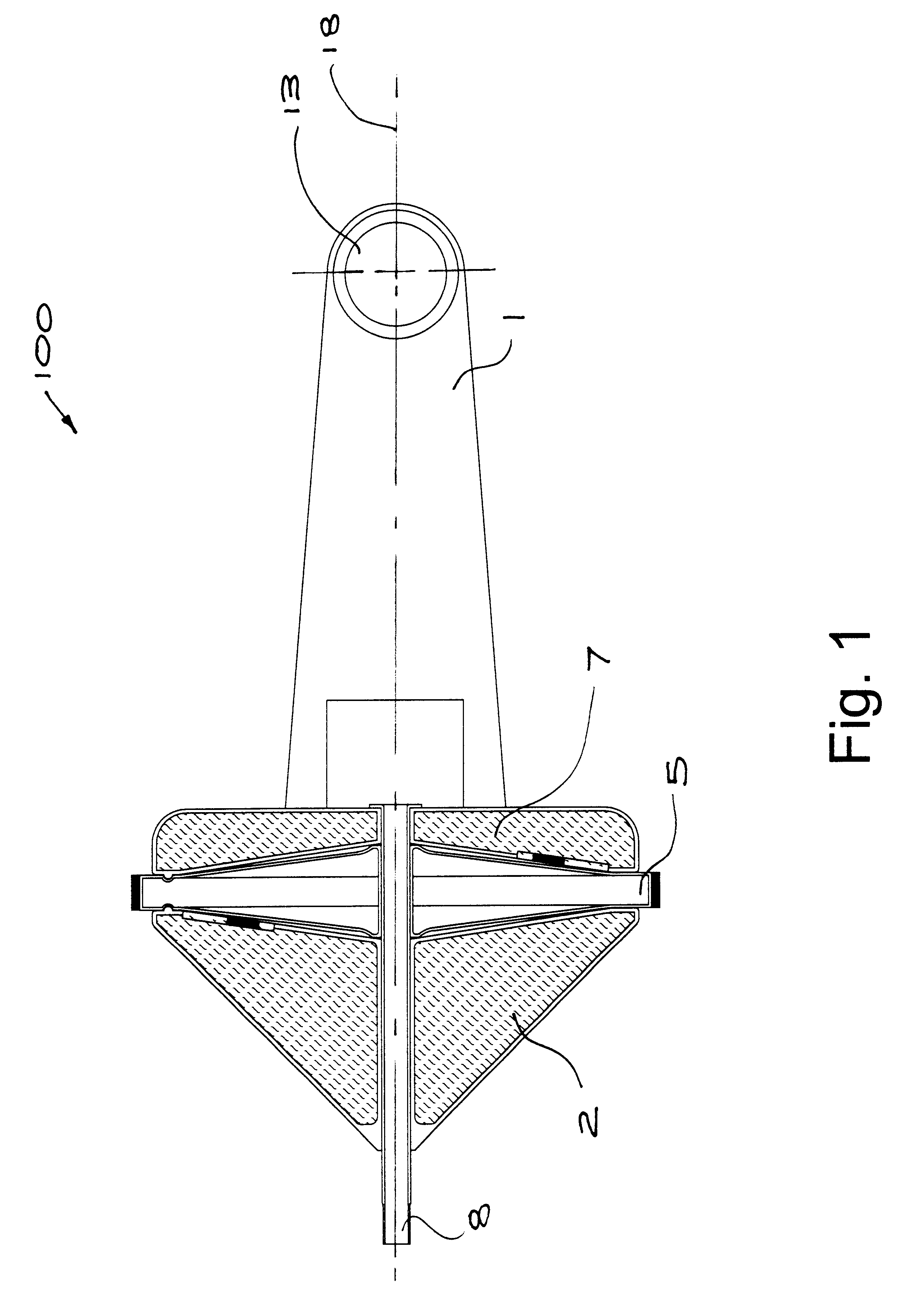
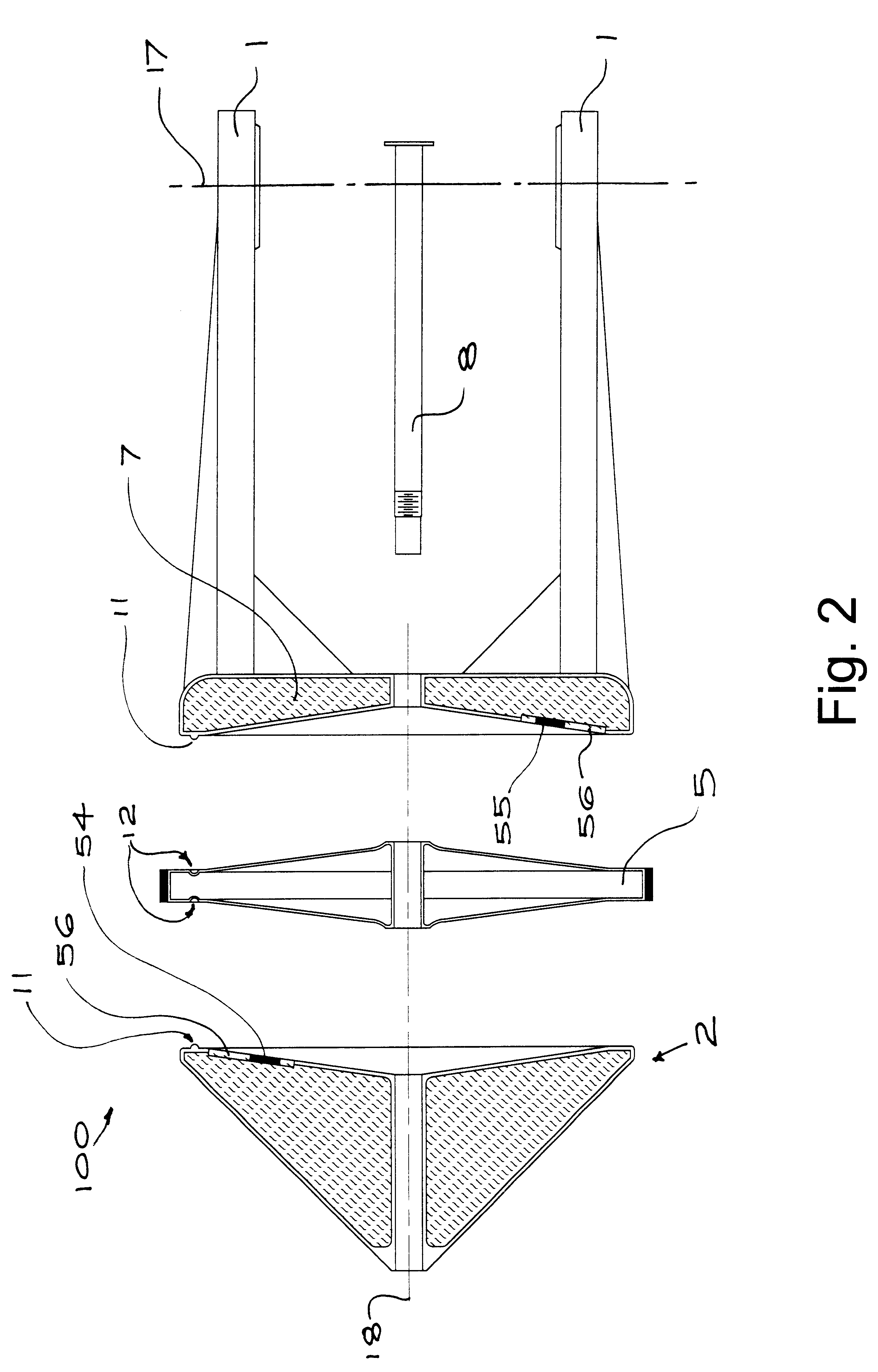
Referring to FIGS. 1 and 2, a fork mount 100 for a telescope is substantially symmetrical about axis 18 and includes two tines 1 connected by a hollow yoke 7 which is adapted to contain ballast material (indicated by the hatching on the drawing). The yoke 7 is fixed to one side of a drive wheel 5, the other side of which is fixed to a generally conical ballast container 2. Bearing apertures 13 are provided in the opposing tines 1 and define an axis 17, orthogonal to axis 18. Both the container 2 and yoke 7 are liquid tight and capable of holding any flowable ballast.

The container 2 and wheel 5 are adapted to be readily separable from the yoke 7. When separated (as shown in FIG. 2) ballast can be added or removed by means of closures 54, 55 in the container 2 and yoke 7 respectively. The closures 54, 55 are each formed in a membrane 56 to equalize atmospheric pressure between inside the vessel and the surrounding atmosphere. The container 2, wheel 5 and yoke 7 are clamped together by...


PUM


Abstract

A support for a telescope includes cavities for holding ballast material for improved stability. The cavities are provided in a fork to which the telescope is mounted, the fork is fixed to a ground-engaging frame for rotation about an axis of the fork. The cavity includes a lowermost conical section having an axis aligned with the axis of rotation.

Description

The present invention relates generally to telescopes and in particular, to mounts for astronomical telescopes.There are two basic types of telescope mounts: altazimuth and equatorial, both having two orthogonal axes of rotation. In the altazimuth mount, one axis (altitude) is horizontal and the other (azimuth) vertical. In the equatorial mount, a first (polar) axis is parallel to the earth's axis (made so by inclining it to the horizontal by an angle equal to the latitude of the viewer) and the second (declination) axis permits adjustment of the angle of inclination. The equatorial mount makes celestial tracking simple: the object is located, the declination axis fixed, and the optical instrument rotated about the polar axis in a direction opposite to, and at a rate equal to the rate of, the earth's rotation. This is known as driving the telescope in right ascension (so known for the path followed by the light receiving end of the instrument). Although tracking of a celestial objec...

Claims


Application Information

Patent Timeline
Patent Type & Authority Patents(United States)
IPC IPC(8): G02B23/16G02B7/00
CPCG02B23/16G02B7/001
Inventor BELCHER, MICHAEL JOHN
Owner BELCHER MICHAEL JOHN
Why Eureka
Try Eureka