Floor groover

a technology of floor groover and groover, which is applied in the direction of other domestic objects, metal working devices, covering/linings, etc., can solve the problems of insufficient adhesive bond between the underside of the floor sheet and the subfloor beneath, and the condition presents both a dangerous condition and an unsightly appearance. , to achieve the effect of uniform cross section

Inactive Publication Date: 2003-11-04
MARTINEZ LEO
View PDF9 Cites 19 Cited by
  • Summary
  • Abstract
  • Description
  • Claims
  • Application Information

AI Technical Summary

Benefits of technology

is to provide a blade for grooving flooring that has a unique configuration and which creates a clean, sharply delineated groove of uniform cross section. Conventional grooving blades are formed as gouges that have a U-shaped cross section and are inclined upwardly and forwardly relative to the direction of movement of the tool. This configuration is one of the reasons that such blades cannot be forced all the way to the edges of the sheets of flooring that abut vertical surfaces, such as walls and cabinets. Rather, because of its upward and forward inclination, the upper leading structure of conventional grooving blades meets the vertical surface before the lower, trailing portion does. The obstruction between the upper portion of the blade and the wall prevents the cutting edge of the blade from progressing all the way to the wall, whereby the groove is terminated prematurely.
To inscribe a groove on the upper surface of a sheet of flooring and within its perimeter, the rear grooving blade and the groove-following guide are temporarily removed from the rear of the tool body. This allows the free movement of the seam-following guide and the front-end grooving blade to travel along guidelines marked on the surface of the flooring. The front-end grooving blade can thereby be utilized to form grooves along a circular pattern, grooves along an elliptical pattern, and other grooves of more complex geometric shapes upon the surface of a sheet of flooring. These grooves are then later filled with molten seam welding material of a different color which hardens and adheres to the flooring surface to provide an aesthetically pleasing pattern or a printed legend on the sheet of flooring.

Problems solved by technology

While in some cases the width of the sheets of the flooring are at least as great as one dimension of the room of the floor to be covered, this is often not the case.
One major problem with laying sheets of flooring in this manner is that the adhesive bond between the underside of the flooring sheets and the subfloor beneath is sometimes inadequate.
Quite often areas of the sheets of the flooring will tend to separate from the subfloor when the adhesive bond between the subfloor and the flooring sheets deteriorates due to age, movement of the subfloor, or improper installation.
This condition presents both a dangerous condition and an unsightly appearance.
It also leads to a significant deterioration of the floor because of the separation that occurs when the edges of adjacent sheets of flooring rise.
When the edges of sheets of flooring separate from the subfloor in this way, moisture and debris often find their way into the crack that forms between the flooring sheets, thus leading to a further deterioration of the floor.
This also creates a condition in which bacteria can thrive, which is highly undesirable in a hospital or kitchen environment.
Plastic sealants of this type are colored to blend in with the color of the flooring sheets, in most cases, so that the seams between the adjacent flooring sheets are not readily apparent.
One principal difficulty with this prior, convention tool is that the user is only able to form a groove up to about eighteen centimeters away from a vertical abutment surface, such as a wall or cabinet base.
Therefore, the installer is left with a problem in that the final distance of about eighteen centimeters cannot easily be grooved.
However, this device presents the installer with essentially the same problem.
Such a hand-held device offers no guidance and no control over either the depth or straightness of the groove.
However, these electrically operated devices are considerably more expensive than hand-operated tools, and can form grooves in flooring only up to about thirty centimeters from the wall or other vertical abutment.
Conventional tools in which the tracking member is located some distance from the grooving blade cannot perform this function adequately.
No conventional groover, either electrically or manually operated, can operate satisfactorily in such an application.
Such conventional tools are neither designed nor recommended to perform this task.

Method used


Image

  • Floor groover
  • Floor groover
  • Floor groover

Examples


Embodiment Construction

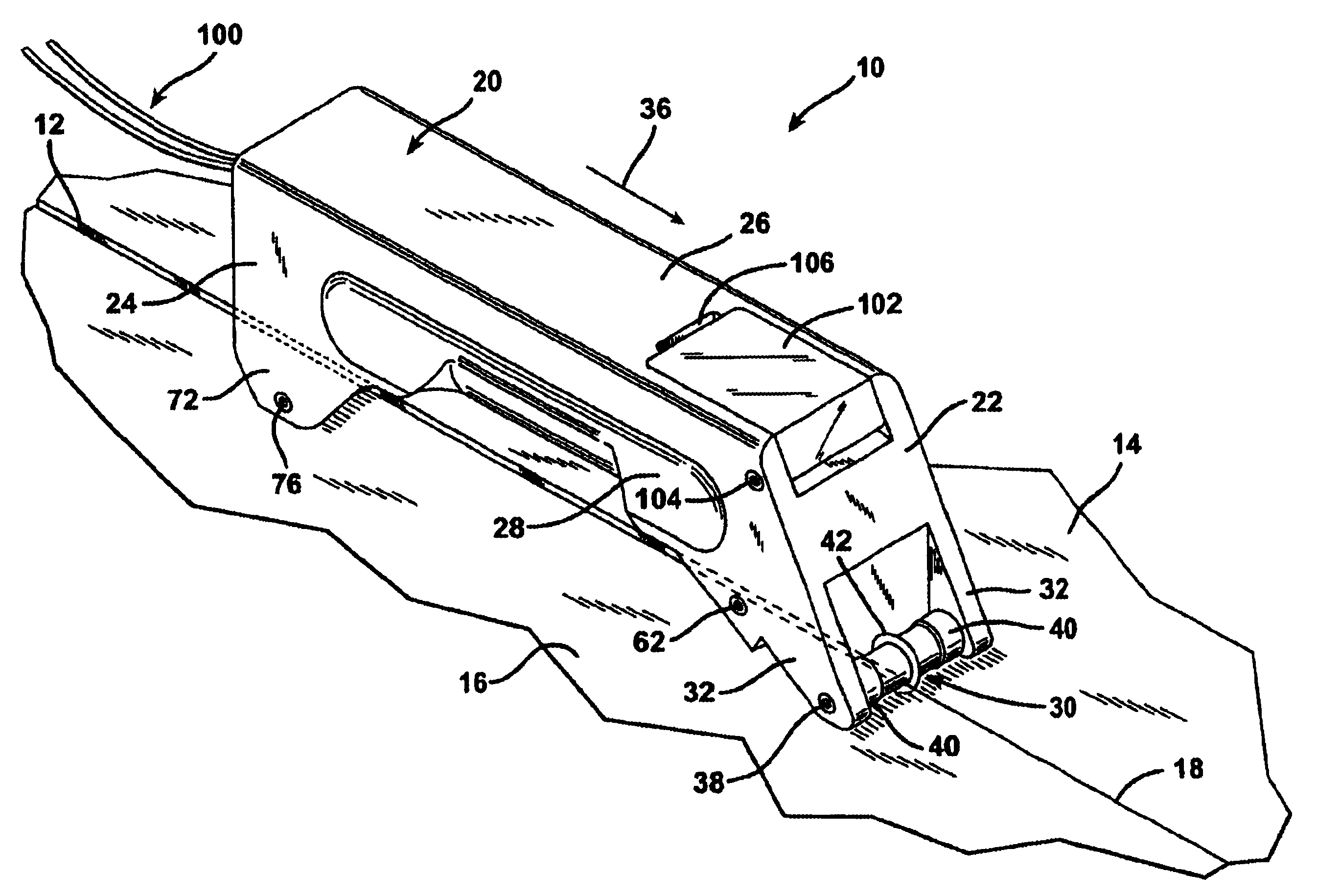
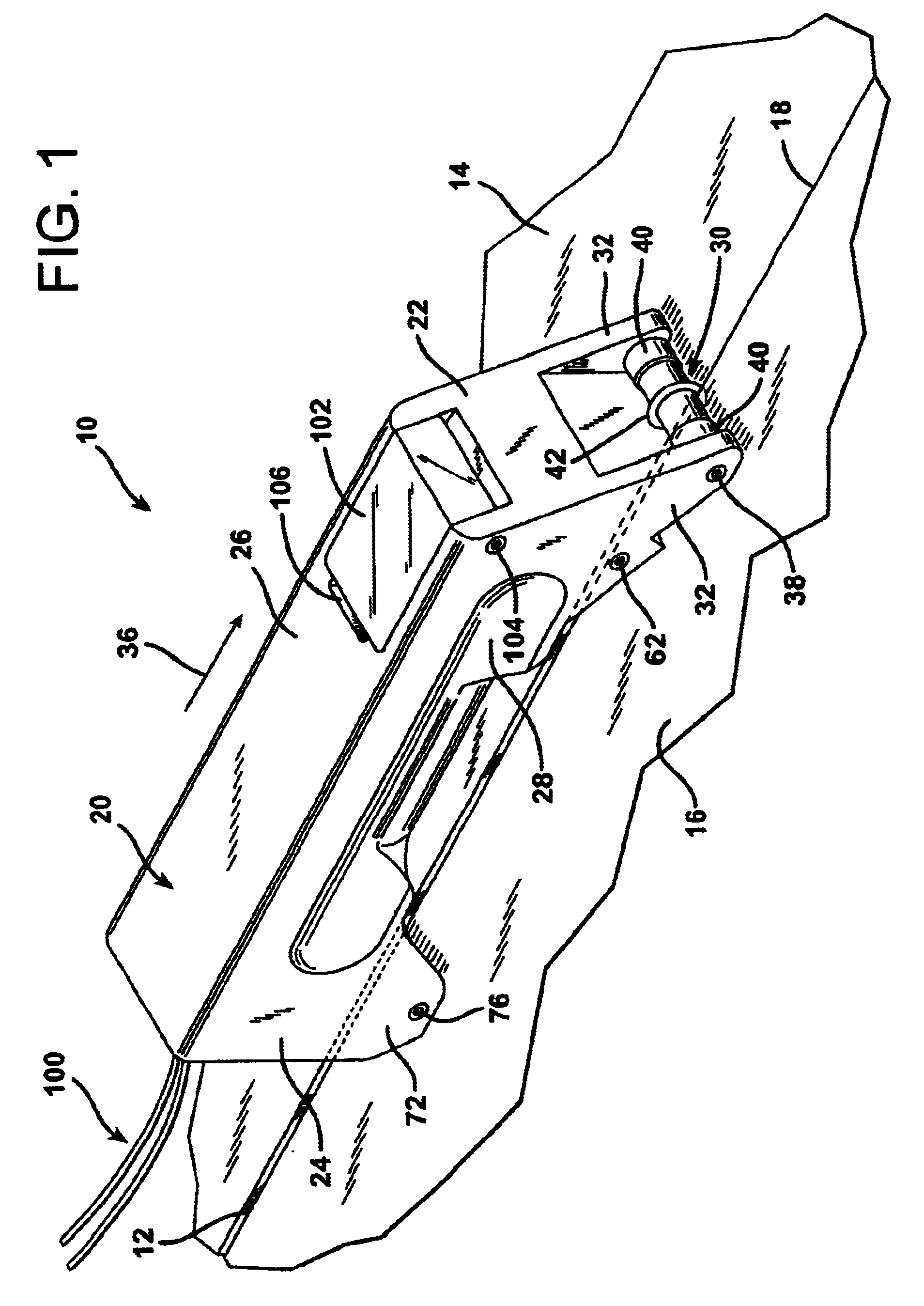
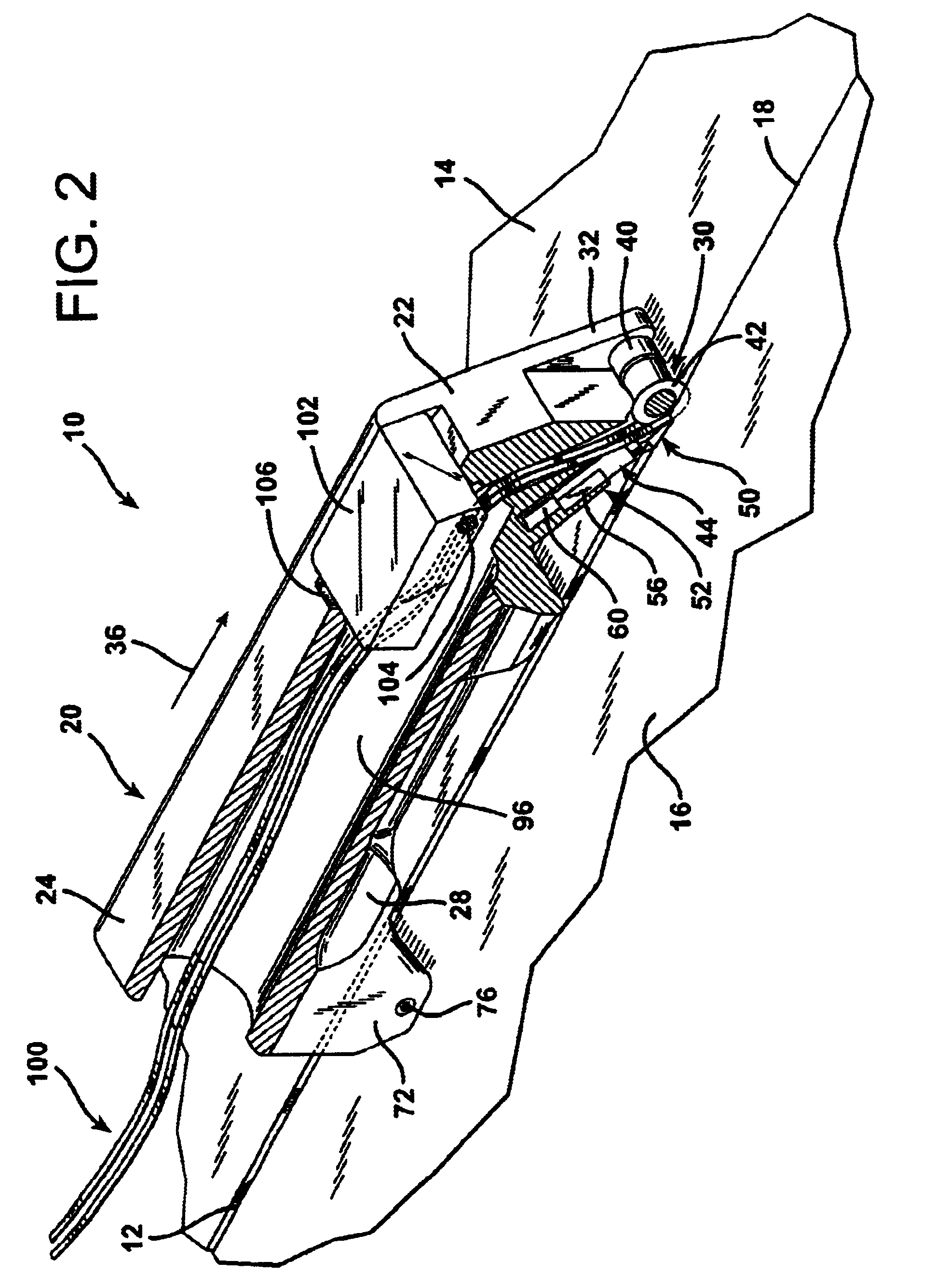
FIGS. 1 through 5 illustrate a manually operated floor grooving tool 10 constructed to create grooves 12 in thin, expansive sheets of flooring which are indicated at 14 and 16. FIGS. 1 through 5 and 8 through 11 show how the floor grooving tool 10 creates grooves 12 at seams 18 between the sheets of flooring 14 and 16, which are disposed with straight linear edges residing in abutting relationship to each other.

The floor grooving tool 10 has an elongated, longitudinally extending body 20 about seventeen centimeters in overall length having opposing front and rear ends indicated at 22 and 24, respectively. An intermediate handgrip portion 26 is formed with a raised undersurface and longitudinally extending, elongated, side depressions 28 that receive the fingertips of the user between the front end 22 and the rear end 24 of the body 20.

As best shown in FIG. 5, the floor grooving tool 10 is provided with a seam-tracking roller 30 mounted to the front end 22 of the body 20 between a pa...


PUM

PropertyMeasurementUnit
widthsaaaaaaaaaa
distanceaaaaaaaaaa
widthaaaaaaaaaa

Abstract

A manually operated floor grooving tool is provided which has opposing front and rear ends with a seam-following roller at its front end and a groove-following roller at its rear end. The tool also employs a pair of grooving blades, one at the front end and one at the rear end. The front grooving blade is inclined upwardly and rearwardly with its cutting tip located just behind the forward axis of rotation of the seam-following guide. The rear-end grooving blade, on the other hand, projects rearwardly from the rear end of the tool and is inclined upwardly and forwardly and behind the groove-following roller. Since the rear-end grooving blade projects beyond the end of the tool in which it is secured, it can complete the formation of the groove all the way up to a vertical abutment. The groove is thereafter filled with sealant in a conventional manner.

Description

1. Field of the InventionThe present invention relates to a manually operated tool designed for use to create grooves in sheets of flooring to receive melted adhesive welding material therein, and grooving blades having a unique configuration and designed for use in such floor grooving tools.2. Description of the Prior ArtAt present, sheets of homogeneous, elastic, PVC, solid vinyl, linoleum, or other rubberized, plastic, or similar flooring are provided in large rolls which can be unrolled at the job site. Such sheets of flooring are typically utilized in hospitals, particularly in surgical areas, as well as in floors of other types of rooms. Such sheets are also used in other types of public buildings, including industrial and commercial buildings. This type of flooring is sometimes used in residential building construction. Smaller sheets in the form of large tiles, one meter square, are also utilized in the same types of applications.While in some cases the width of the sheets o...

Claims


Application Information

Patent Timeline
Patent Type & Authority Patents(United States)
IPC IPC(8): B26B29/06B26B29/00B26D3/06B26D3/00B29C65/10B29C65/12
CPCB26B29/06B26D3/065B29C66/836B29C65/12B29C66/1142B29C66/43B29L2031/732E04F13/08B29C66/1224B29C66/1228B29C2793/0081B29C66/8612B29C65/18B29C65/42B29C66/71B29K2021/00B29K2027/06
Inventor MARTINEZ, LEO
Owner MARTINEZ LEO
Why Eureka
Try Eureka