Control system for marine engine

a control system and engine technology, applied in the direction of electrical control, marine propulsion, vessel construction, etc., can solve the problems of not maintaining the desired air/fuel ratio at relatively higher engine speed and larger throttle opening, experiencing an uneasy feeling that something is wrong with the engine, and not performing well in control mod

Inactive Publication Date: 2003-11-18
YAMAHA MARINE KK
View PDF9 Cites 17 Cited by
  • Summary
  • Abstract
  • Description
  • Claims
  • Application Information

AI Technical Summary

Problems solved by technology

It has been found that although such a D-j control scenario performs well at lower engine speeds and smaller throttle openings, it does not maintain desired air / fuel ratios as well as at relatively higher engine speeds and larger throttle openings.
In particular, it has been found that a rider of a watercraft using such a system can experience an uneasy feeling that something is wrong with the engine when the controller switches from the D-j control mode to the .alpha.-N control mode, and vice versa.
However, despite the performance disparity between the D-j and .alpha.-N control modes, one of these control modes can be used for all engine speeds if the other is un-usable due to sensor malfunction.
Although this control mode does not perform as well at low engine speeds and small throttle openings, it will allow the engine to operate with only minor or no changes in engine behavior that are noticeable by a rider.

Method used


Image

  • Control system for marine engine
  • Control system for marine engine
  • Control system for marine engine

Examples


Embodiment Construction

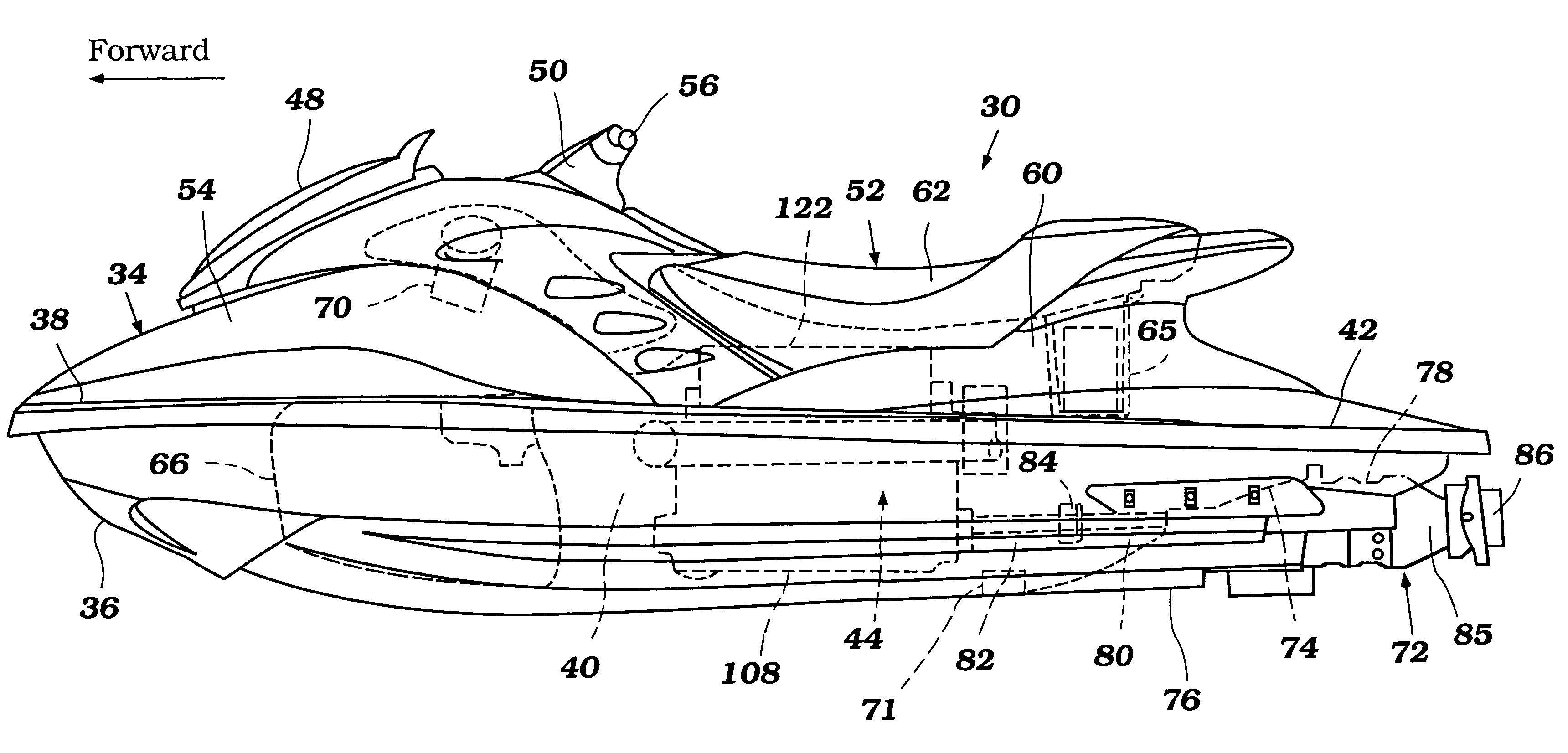
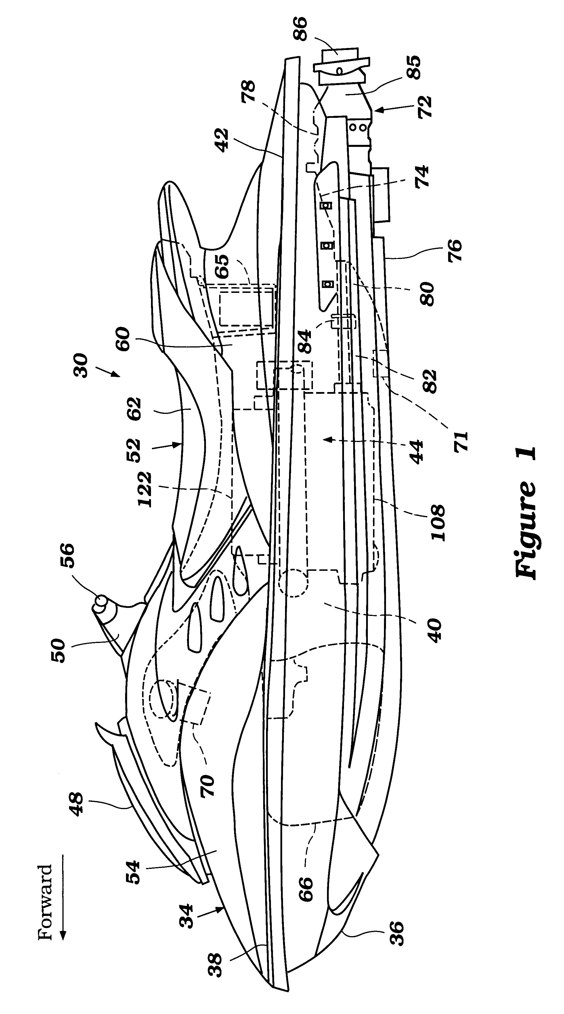
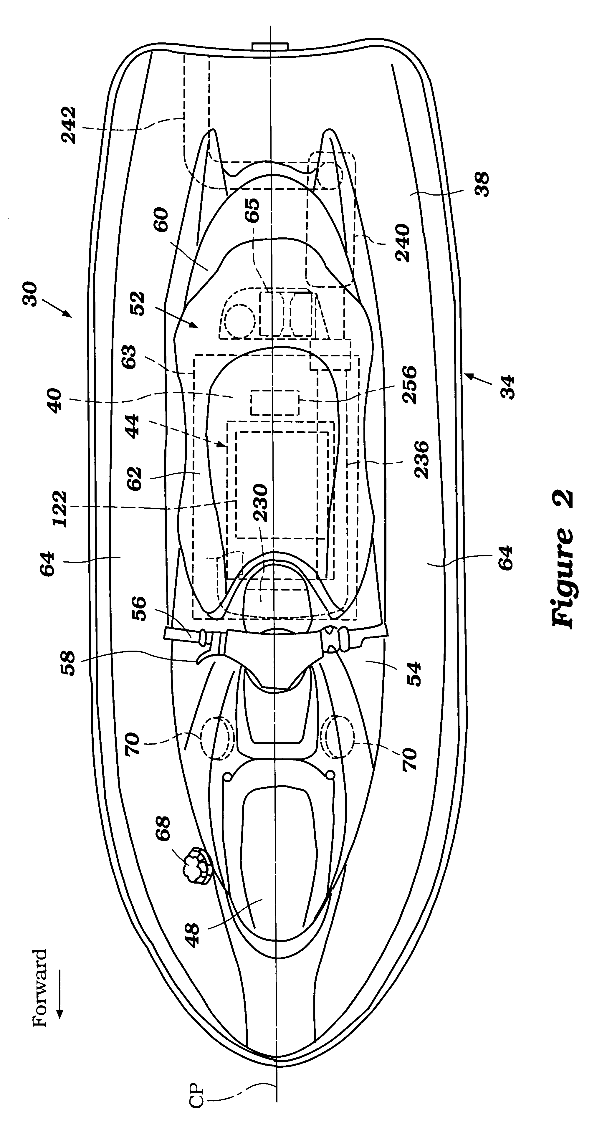
With reference to FIGS. 1-3, an overall construction of a personal watercraft 30 configured in accordance with the present invention will be described. The watercraft 30 is described in the context of a personal watercraft. The watercraft 30, however, can be other types of watercraft such as jet boats or other motor boats inasmuch as they transfer to planing position from a trolling position. Applicable watercraft will become apparent to those of ordinary skill in the art.

The personal watercraft 30 includes a hull 34 generally formed with a lower hull section 36 and an upper hull section or deck 38. Both the hull sections 36, 38 are made of, for example, a molded fiberglass reinforced resin or a sheet molding compound. The lower hull section 36 and the upper hull section 38 are coupled together to define an internal cavity 40. An intersection of the hull sections 36, 38 is defmed in part along an outer surface gunwale or bulwark 42. The hull 36 houses an internal combustion engine 4...


PUM


Abstract

A personal watercraft includes a hull and a jet propulsion unit that propels the hull. An engine powers the jet propulsion unit. The engine includes an air intake system to introduce air to a combustion chamber. The intake system includes a throttle valve to regulate an amount of the air. The throttle valve is moveable generally between a closed position and an open position. A fuel injection system is arranged to spray fuel for combustion in the combustion chamber. The engine also includes an intake pressure sensor, a throttle valve position sensor and an engine speed sensor. A control device is provided to control an amount of the fuel using either a D-j control mode or an alpha-N control mode. The D-j control mode is based upon a signal from the intake pressure sensor and a signal from the engine speed sensor. The alpha-N control mode is based upon a signal from a throttle valve position sensor and the signal from the engine speed sensor. The control device uses the D-j control mode either when the throttle valve is relatively in a low opening degree range or when an engine speed is relatively in a low speed range, and uses the alpha-N control mode either when the throttle valve is relatively in a high opening degree range or when the engine speed is relatively in a high speed range. Additionally, the control device is configured to detect the malfunction of the throttle valve position sensor and the pressure sensor. If the throttle valve position sensor malfunctions, the control device uses only the D-j control mode. If the pressure sensor malfunctions, the control device uses only the alpha-N control mode.

Description

PRIORITY INFORMATIONThis application is based on Japanese Patent Application No. 2001-037048, filed Feb. 14, 2001, and Japanese Patent Application No. 2001-288523, filed Sep. 21, 2001, the entire contents of both being hereby expressly incorporated by reference herein.1. Field of the InventionThe present invention relates generally to a control system for a marine engine, and more particularly to an improved control system for a marine engine that controls an amount of fuel injected by one or more fuel injectors.2. Description of Related ArtRelatively small watercraft such as, for example, personal watercraft have become very popular in recent years. This type of watercraft is quite sporting in nature and carries one or more riders. A hull of the watercraft typically defines a rider's area above an engine compartment. An internal combustion engine powers a jet propulsion unit that propels the watercraft by discharging water rearwardly. The engine lies within the engine compartment i...

Claims


Application Information

Patent Timeline
Patent Type & Authority Patents(United States)
IPC IPC(8): F02B61/00F02B61/04B63H21/21F02D29/02F02D41/04F02D41/18F02D45/00
CPCF02B61/045
Inventor KANNO, ISAO
Owner YAMAHA MARINE KK
Why Eureka
Try Eureka