Irreversible circuit component and communication device

Inactive Publication Date: 2003-11-18
MURATA MFG CO LTD
View PDF3 Cites 2 Cited by
  • Summary
  • Abstract
  • Description
  • Claims
  • Application Information

AI Technical Summary

Benefits of technology

With the above-described structure, the pressure used when the permanent magnet and the metal case are mounted, is divided and applied to both the resin case and the internal component. Thus, the pressure applied to the internal component is reduced. This suppresses the internal component from being broken.
Preferably, the number of the at least two contact-portions is three. Thereby, the positional shifting of the ferrite (specifically, a disk-shaped ferrite) can be prevented.
Preferably, the resin member and the resin case are made of a material selected from either a liquid crystal polymer or PPS. The liquid crystal polymer and PPS have high heat resistance and low loss. Thus, the irreversible circuit component can be provided with high reliability.
A communication device in accordance with the present invention includes the irreversible circuit component having the above-described characteristics. Thus, the communication device can be provided with low cost and high reliability.

Problems solved by technology

Problems arise especially when the under face of the matching capacitor element C contacts both of the lower case 4 and the resin case.

Method used


Image

  • Irreversible circuit component and communication device
  • Irreversible circuit component and communication device
  • Irreversible circuit component and communication device

Examples


first embodiment

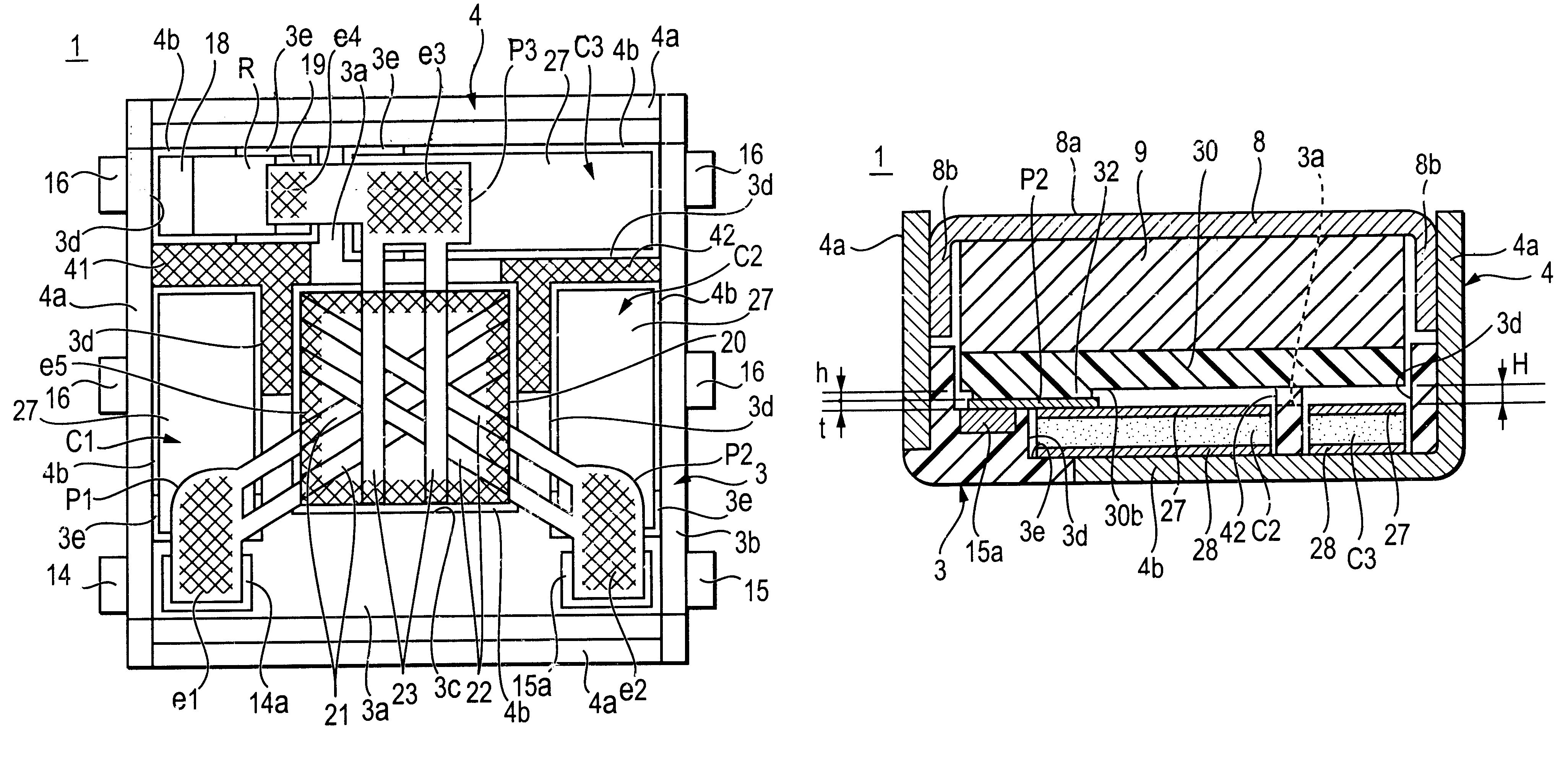
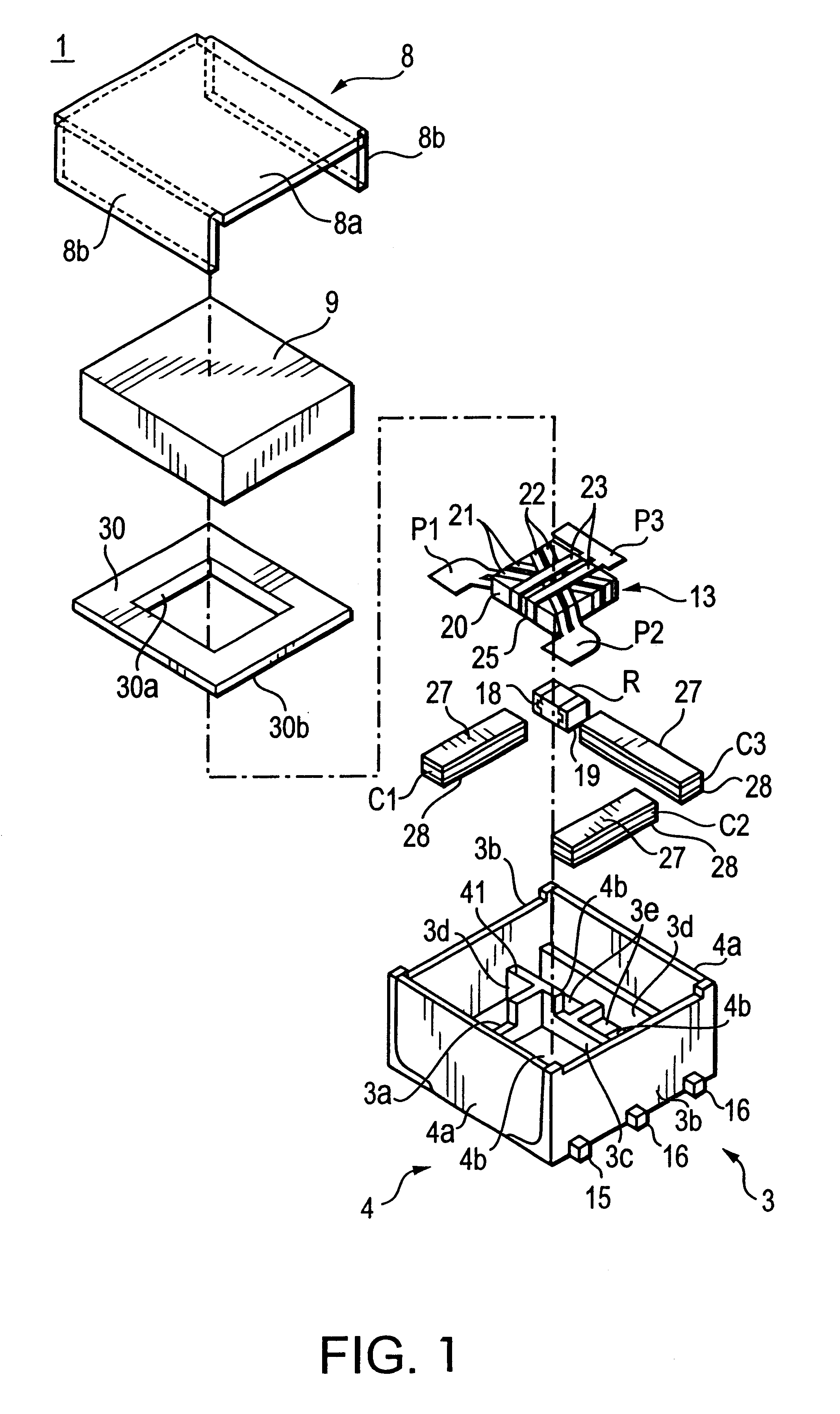
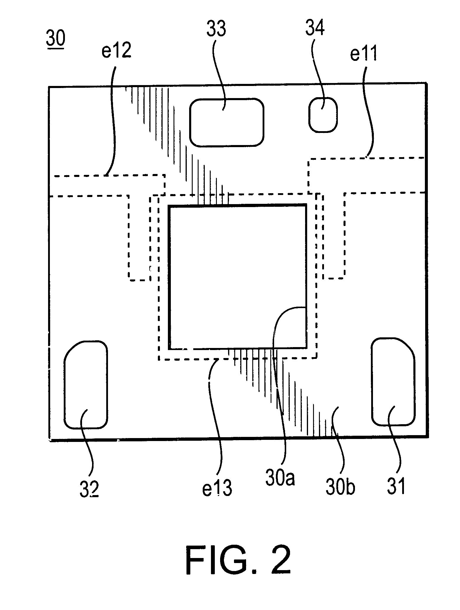
FIG. 1 is an exploded perspective view showing the structure of an irreversible circuit component according to a first embodiment of the present invention. FIG. 2 is a plan view of the resin member 30 viewed from the side of the under face 30b thereof. FIG. 3 is a plan view showing the inside of the irreversible circuit component 1 shown in FIG. 1. FIG. 4 is a perspective view showing the appearance of the irreversible circuit component 1 of FIG. 1 after the assembly is completed. The irreversible circuit component 1 is a lumped-constant isolator.

The lumped-constant isolator 1 comprises the upper case 8 made of magnetic metal, the lower case 4 made of magnetic metal, the resin case 3, a center electrode assemblage 13, the permanent magnet 9, the resistance element R, the matching capacitor elements C1 to C3, a resin member 30, and so forth, as shown in FIG. 1.

case 4

The lower case 4 comprises side walls 4a and the bottom wall 4b. The lower case 4 is formed integrally with the resin case 3 by an insert-molding process. Two ground terminals 16 are provided so as to extend respectively from a pair of sides opposed to each other of the bottom wall 4b of the lower Moreover, the upper case 8 has a rectangular shape in the plan view thereof, and comprises the upper wall 8a and the side walls 8b on the right and left sides. The lower case 4 and the upper case 8 are formed by punching a sheet material with a high magnetic permeability, e.g., made of Fe or silicon steel, bending, and plating the surface with Cu or Ag.

As regards the center electrode assemblage 13, three center electrodes 21 to 23 are arranged on the top side of a rectangular-shaped microwave ferrite 20 so as to intersect substantially at intervals of 120.degree. with insulating sheets (not shown) being interposed between them. The center electrodes 21 to 23 have ports P1 to P3 at first e...

second embodiment

FIG. 10 shows a irreversible circuit component according to a second embodiment of the present invention. The resin case 3 of the lumped-constant isolator 1a of the second embodiment has substantially the same structure as the resin case 3 of the above-described lumped-constant isolator 1 of the first embodiment. In particular, convexities 41 and 42 which are the same as those shown in FIG. 3 are formed on the bottom 3a of the resin case 3. The convexities 41 and 42 contact the resin member 30.

In the second embodiment, the under face 30b of the resin member 30 is flat with no convexity being formed thereon. Moreover, the center electrodes 21 to 23 are bent so as to contact the terminal electrodes 27 on the hot sides of the matching capacitor elements C1 to C3 and the terminal electrode 19 on the hot side of the resistance element R, respectively. As regards the structure of the isolator 1a, the terminal electrodes 27 on the hot sides press the ports P1 to P3 by utilization of the sp...


PUM


Abstract

In an irreversible (non reciprocal) circuit component, a resin member is arranged between a permanent magnet, and a matching capacitor or the like. The port of a center electrode and the terminal electrode on the hot side of the matching capacitor are electrically connected on the top face of the matching capacitor element, and also, an output lead-out electrode is electrically connected to them. A convexity may be formed on the under face of the resin member, and a convexity is formed on the bottom of the resin case. The convexity of the resin case contacts the under face of the resin member.

Description

1. Field of the inventionThe present invention relates to an irreversible circuit device and a communication device.2. Description of the Related ArtGenerally, a lumped-constant isolator (one type of irreversible circuit device) employed in mobile communication devices such as portable telephones or the like has a function of allowing a signal to pass only in the transmission direction and blocking the transmission of a signal in the reverse direction. Moreover, for recent mobile communication devices, higher reliability and lower cost have been required, due to the type of use. Accordingly, for the lumped-constant isolators as well, higher reliability and lower cost have been strongly required.The above-described lumped-constant isolators each comprise a permanent magnet, a ferrite to which a DC magnetic field is applied, a plurality of center electrodes arranged on the ferrite, a capacitor element for matching, a resin member arranged between the permanent magnet and the matching ...

Claims


Application Information

Patent Timeline
Patent Type & Authority Patents(United States)
IPC IPC(8): H01P1/387H01P1/32H01P1/383H01P1/36
CPCH01P1/387
Inventor HASEGAWA, TAKASHI
Owner MURATA MFG CO LTD
Why Eureka
Try Eureka