
Cooler for electronic unit and electronic unit

a technology for electronic units and cooling devices, applied in the direction of electrical apparatus casings/cabinets/drawers, stoves or ranges, domestic stoves, etc., can solve the problems of reduced heat transfer performance, insufficient cooling performance, and difficult to ensure the installation place of the fan-disposing space bottom surface portion

Inactive Publication Date: 2003-11-25
LENOVO PC INT
View PDF2 Cites 26 Cited by
  • Summary
  • Abstract
  • Description
  • Claims
  • Application Information

AI Technical Summary

Benefits of technology

Another object of the invention is to provide an electronic unit equipped with a heat sink and a heat pipe having enhanced performance.
The high heat-conductive metal member is equipped integrally with the heat-generating-body side portion, the fan-disposing-space bottom surface portion, and the hanging portion, and is joined to the heat sink. Therefore, satisfactory cooling performance in the fan disposing space is guaranteed, while satisfactory assembly performance of the electronic-unit cooler is being assured. Because the high heat-conductive metal member also defines the fan disposing space at the hanging portion, the cooling effect of the high heat-conductive metal member in the fan disposing space is increased.

Problems solved by technology

In the aforementioned CPU of Published Unexamined Patent Application No. 2000-323880, the cooling performance is insufficient, because only the heat pipe transfers the heat of the CPU toward the fan.
As a result, the heat transfer performance is reduced.
If the size of the horizontal section of the fan disposing space is made equal to the size of the fan, it will become difficult to assure an installation place for the fan-disposing-space bottom surface portion of the heat pipe, particularly when there is an upper inlet port.

Method used


Image

  • Cooler for electronic unit and electronic unit
  • Cooler for electronic unit and electronic unit
  • Cooler for electronic unit and electronic unit

Examples


Embodiment Construction

A preferred embodiment of the present invention will be described with reference to the drawings.

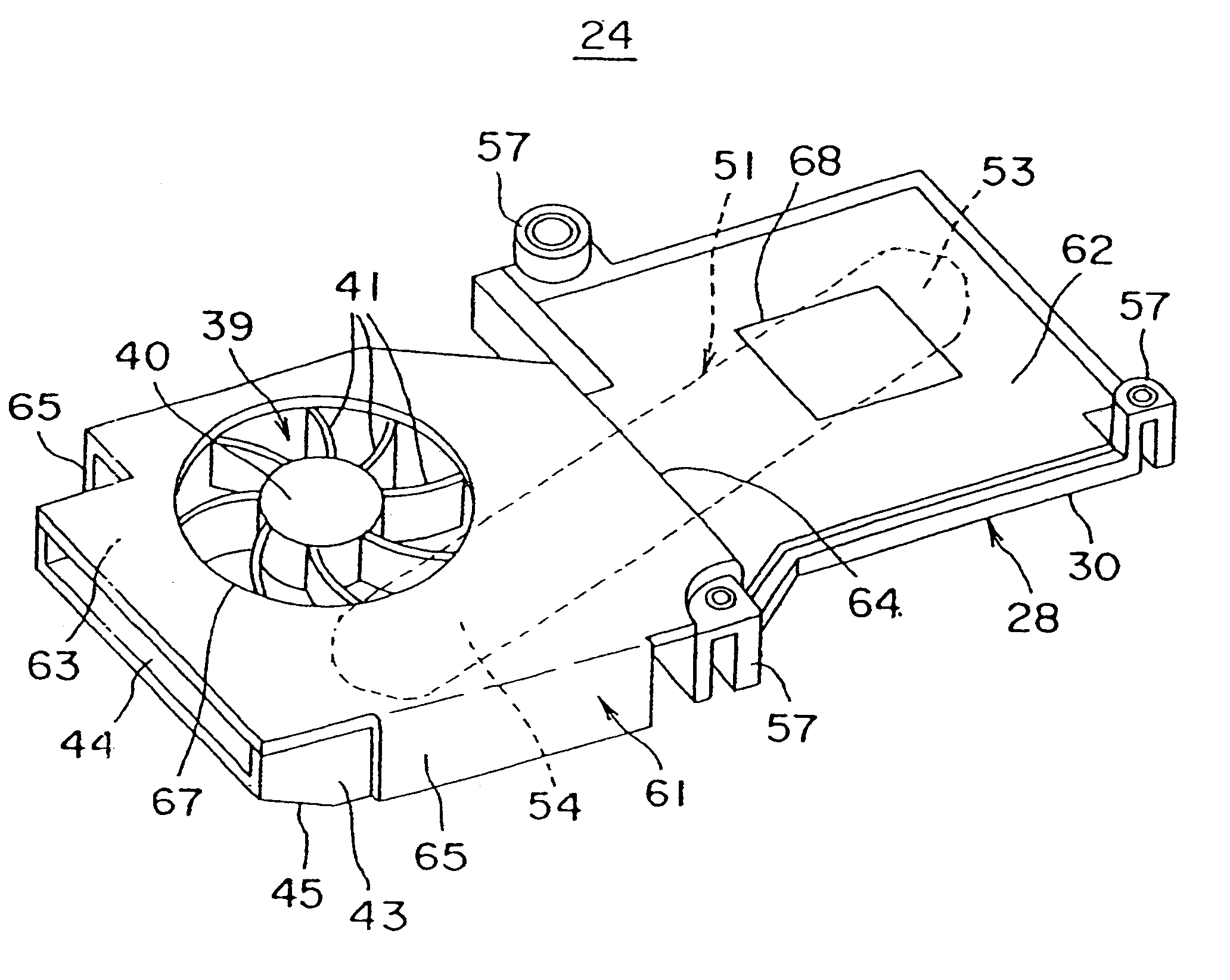
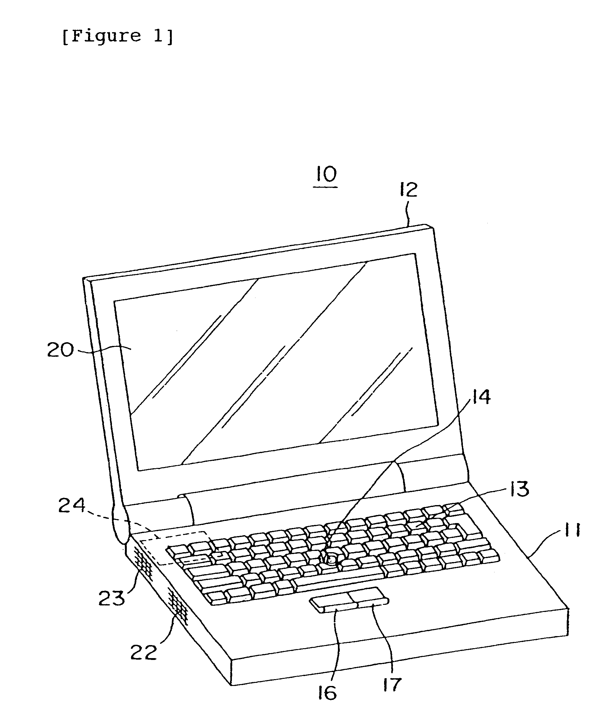
FIG. 1 is a perspective view of a notebook-sized personal computer 10. The notebook-sized personal computer 10 has a main body 11 and a cover 12. The cover 12 is joined to the main body 11 and rear edge portion of the main body 11 at its lower edge portion so that it is freely rotatable and which is freely opened and closed on the top surface of the main body 11. In the top surface of the main body 11, there are disposed a keyboard 13, a track point 14 provided in approximately the central portion of the keyboard 13 to move a cursor on the screen of a liquid crystal display 20, and a left click button 16 and a right click button 17 provided in the laterally central portion and in front of the keyboard 13. The liquid crystal display 20 is mounted in the inner surface of the cover 12 and displays an image. In the left side portion of the housing of the main body 11, an inlet port 22 and an...


PUM


Abstract

A CPU cooler is provided for effectively cooling, for example, a CPU chip mounted in a notebook-sized personal computer. An aluminum die casting is equipped with a right portion for covering a CPU package, and a left portion which is coplanar with the right portion and continuous to the right portion, thus forming a fan disposing space. A flat heat pipe is mounted on a bottom surface of the right and left portions and extends linearly. A copper plate is equipped with a first horizontal plate portion for covering the bottom surface of the right portion and the flat heat pipe, and a second horizontal plate portion which faces a second top surface in a height direction and defines the bottom side of a fan disposing space.

Description

1. Field of the InventionThe present invention relates to a cooler for an electronic unit that is used for cooling a central processing unit (CPU) in a notebook-sized personal computer, and an electronic unit with the cooler, and more particularly to an electronic-unit cooler and an electronic with the cooler in which the cooling performance has been enhanced.2. Related ArtIn notebook-sized personal computers, the amount of heat generated in a CPU increases, as the CPU is operated at a higher speed. For this reason, there has been a demand for cooling of the CPU, and a wide variety of coolers for an electronic unit have been proposed.The CPU cooler disclosed in Published Unexamined Patent Application No. 2000-323880 utilizes a heat pipe. The heat pipe transfers the heat of a CPU to the entire keyboard and discharges the heat to the outside through the entire keyboard. The heat pipe also transfers the heat to a cooling fan and discharges the heat by forced cooling.In the CPU cooler d...

Claims


Application Information

Patent Timeline
Patent Type & Authority Patents(United States)
IPC IPC(8): G06F1/20H05K7/20F28D15/02
CPCG06F1/203
Inventor KAWASHIMA, NOBUYUKIMATSUI, YOHICHIHORIUCHI, MITSUO
Owner LENOVO PC INT
Learn More