Breathing device for internal combustion engine

a technology for internal combustion engines and breathing devices, which is applied in the direction of engine sealings, charge feed systems, and addition of non-fuel substances to fuel, etc., and can solve the problems of increased engine size, high assembly cost, and stringent design limitations

Inactive Publication Date: 2003-12-09
KAWASAKI HEAVY IND LTD
View PDF4 Cites 18 Cited by
  • Summary
  • Abstract
  • Description
  • Claims
  • Application Information

AI Technical Summary

Benefits of technology

With the breathing device for the combustion engine according to the present invention, as compared with the structure in which the check valve is disposed inside the rocker arm chamber or the crankcase such as in the prior art, the structure around the check valve can be simplified to an extent that is resulted from elimination of the use of any member which would otherwise be required to support the check valve. Accordingly, it is possible to reduce the cost and the size of the combustion engine, with the design limitation on the combustion engine being lessened.
This substantially eliminates the use of any special casing and sealing mechanism in the breathing device and, therefore, the number of component parts can advantageously be reduced, resulting in further reduction in cost.
Where the breathing device is constructed in this way, the rigidity of the check valve can be sufficiently lowered by the slot with no need to increase the length of the check valve and, therefore, the check valve can have an increased response to opening or closing with small size. Since the check valve can be made in small size in this manner, the check valve can easily be disposed in the head gasket where a space is limited for interposition thereof between the cylinder block and the cylinder head. Also, where the check valve is mounted on the head gasket with the support portion thereof fixedly secured to the head gasket by a fixing member, such as a rivet, the presence of the elongate slot is effective to minimize reduction in sealability which would otherwise occur when the check valve warps, and any possible increase of the rigidity can advantageously be avoided, which would occur as a result of deformation of the support portion of the check valve to a concave shape in a transverse section.
In such case, because of the presence of the recess defined in the portion of the head gasket confronting the intermediate portion of the check valve, it is possible to avoid any possible sticking of the check valve to the head gasket by the effect of the viscosity of the oil component.
Formation of the check valve integrally with the head gasket makes it possible for a valve mechanism of the breathing device to be simplified in structure along with reduction in number of component parts used.
In a still further preferred embodiment of the present invention, the head gasket is in the form of a metallic plate coated with a rubber material. The use of this head gasket is effective to increase the sealability between the check valve and the head gasket.

Problems solved by technology

However, in the breathing devices, since the structure is complicated and the number of component parts is relatively large, the cost of assembling is high and the design limitation is stringent.
Also, while the check valve must have a sufficient response to opening or closing and a sufficient sealability in order to secure the performance, the check valve tends to become bulky in order to fulfill the requirements, resulting in increase in size of the engine.
The engine with the check valve disposed inside the crank case is also known, but even this engine has problems similar to those discussed above.

Method used


Image

  • Breathing device for internal combustion engine
  • Breathing device for internal combustion engine
  • Breathing device for internal combustion engine

Examples


third embodiment

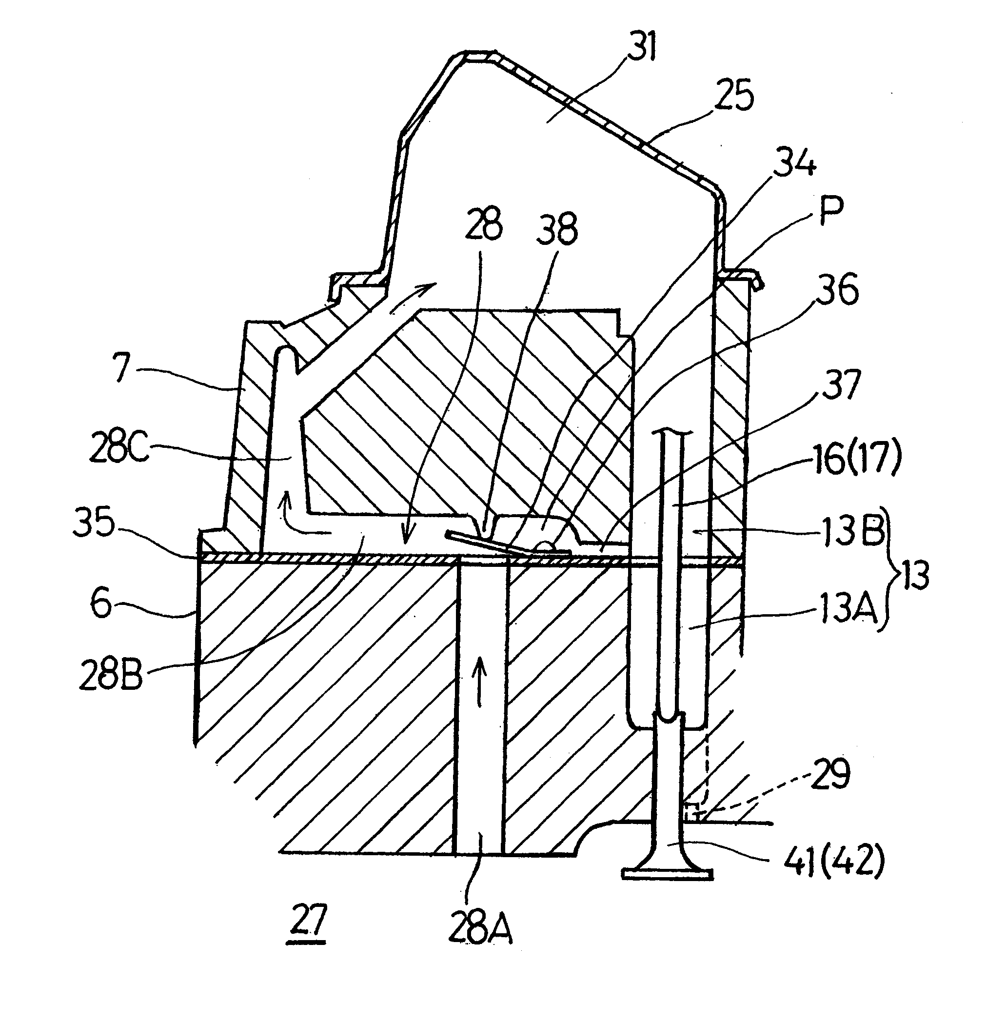
It is to be noted that the check valve 34 employed in the practice of the present invention may be of a structure similar to the check valve 34A shown in FIGS. 6 and 7, that is, may have the elongate slot shown by 39 in FIGS. 6 and 7. Even though the check valve 34 shown in FIGS. 8 and 9 has the elongate slot as is the case with the check valve 34A shown in FIGS. 6 and 7, undesirable sticking of the check valve 34 to the head gasket 35 can be effectively avoided.

FIG. 10 illustrates, in a plan view, the check valve 34B according to a fourth preferred embodiment of the present invention. In this embodiment, the check valve 34B is defined integrally with a section of the head gasket 35. Specifically, the check valve 34B is defined by forming a generally U-shaped crevice 40 in the head gasket 35 so as to leave a correspondingly U-shaped flap which in effect acts as the check valve 34B.

fourth embodiment

described above, since the check valve 34B is formed integrally with the section of the head gasket 35, the structure necessary to form the check valve 34B can be simplified, accompanied by reduction in number of the component parts.


PUM


Abstract

To provide a breathing device for an internal combustion engine, wherein the structure around the check valve is simplified so that the engine as a whole can be manufactured compact, the breathing device includes a check valve (34) for fluid connecting, a crank chamber (27) and a rocker arm chamber (31) in the combustion engine. The check valve (34) is disposed in a head gasket (35) that is interposed between a cylinder block (6) and a cylinder head (7). The check valve (34) is in the form of a reed valve separate from the head gasket (35) and is supported by the head gasket (35) by means of a rivet (36).

Description

1. Field of the InventionThe present invention relates to an internal combustion engine and, more particularly, to a breathing device used in the engine to relieve an internal pressure inside a crankcase.2. Description of the Prior ArtA breathing device is known as a device which, when an internal pressure inside a crank chamber increases as a result of movement of a piston under suction and expansion strokes, operates to suck a blow-by gas from the crank chamber and then introduce it into a rocker arm chamber and also, if necessary, to circulated the blow-by gas towards an inside of an air cleaner. The breathing device is generally provided with an oil separation mechanism for separating an oil component from the blow-by gas during circulation of the blow-by gas. This oil separation mechanism generally includes an oil separation chamber and a check valve both disposed inside a rocker cover mounted atop a cylinder head of the engine.However, in the breathing devices, since the struc...

Claims


Application Information

Patent Timeline
Patent Type & Authority Patents(United States)
IPC IPC(8): F01M13/00F02M25/06
CPCF01M13/0011F02M25/06F16J15/0818F16J15/064F01M2013/0016Y02T10/121F16J2015/0868Y02T10/12
Inventor NAKAMIZO, KEIICHIAKASE, SHINYA
Owner KAWASAKI HEAVY IND LTD
Why Eureka
Try Eureka