The use of
graphite as a material for the sleeve is, of course, suitable only if carbon is insoluble in the melt to be atomized. This holds for melts that contain neither metals nor iron or
chromium oxides. When using
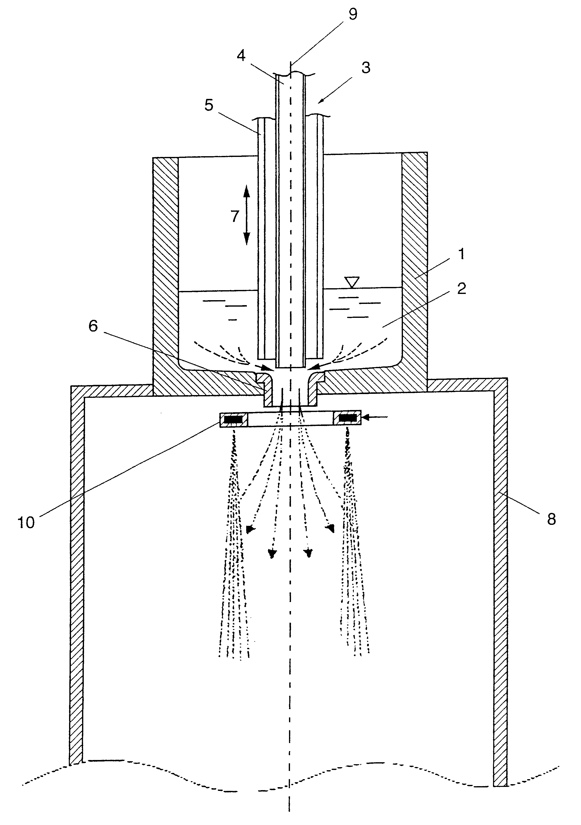
graphite as a material for the external tube, this will constitute a particularly cost-effective wear part which, at the same time, offers the opportunity to effectively counteract the closing up of the outlet opening.
Advantageously, the configuration according to the invention is devised such that the outlet opening in the form of a
nozzle block and the external tube or sleeve are made of an
electrically conductive material, in particular
graphite, whereby, if also the
nozzle block is made of an
electrically conductive material,
electric heating may be effected in a simple manner, for instance, by the formation of an
electric arc between the sleeve and the
nozzle block in the region of the inlet opening and the
propellant jet feed so as to enable the assurance of a constant
nozzle geometry during operation. When providing such heating in the region of the nozzle gap it is still feasible to make use of another important
advantage of the configuration according to the invention. After all, it basically applies that the droplets or respective solidifying particles will become finer the higher the vapor temperature, this being due, inter alia, to an accordingly enhanced
rheology of the droplets. However, high final vapor temperatures usually call for an accordingly cumbersome vapor generation and an accordingly demanding supply of high-temperature vapor to the lance. Due to the fact that the final heating or final
superheating of vapor may be effected, for instance, by an
electric arc,
superheating of the vapor to a maximum of 1600.degree. C. may be reached by substantially lower vapor temperatures and, for instance, vapor temperatures of about 700.degree. C. at a maximum
vapor pressure of 10 bars. The generation of vapor is, thus, accordingly more cost-effective, the
temperature load on the vapor lance, thus, being strongly reduced. The
superheating of "cold vapor" in the nozzle region, inter alia, will cause the lance itself to be relieved from
vapor pressure, because in that region the pressure has already been converted into jet speed, the jet tube thus being subjected to a substantially lower
thermal load.
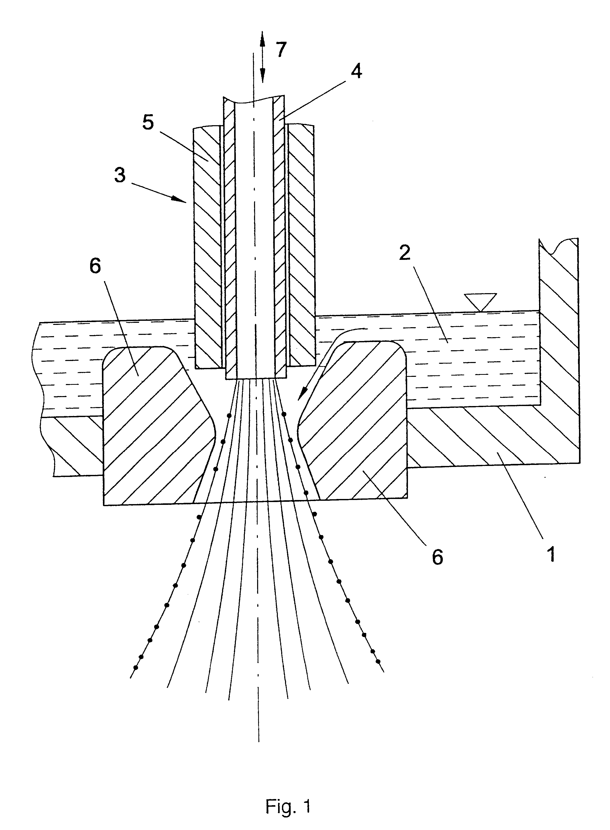
According to another preferred embodiment, the central tube of the lance is made of a
ceramic material or high-temperature-resistant steel, whereby the requirements for a precise jet geometry may be more readily observed. While
thermal deformation and optionally even the melting off of the lance mouth has to be taken into account in conventional lances made of steel, it is feasible, by using a sleeve made of an accordingly temperature-resistant material, to keep the direct action of the slag away from the mouth of the central tube or internal tube such that the constancy of the jet geometry may be maintained over an extended period of time.
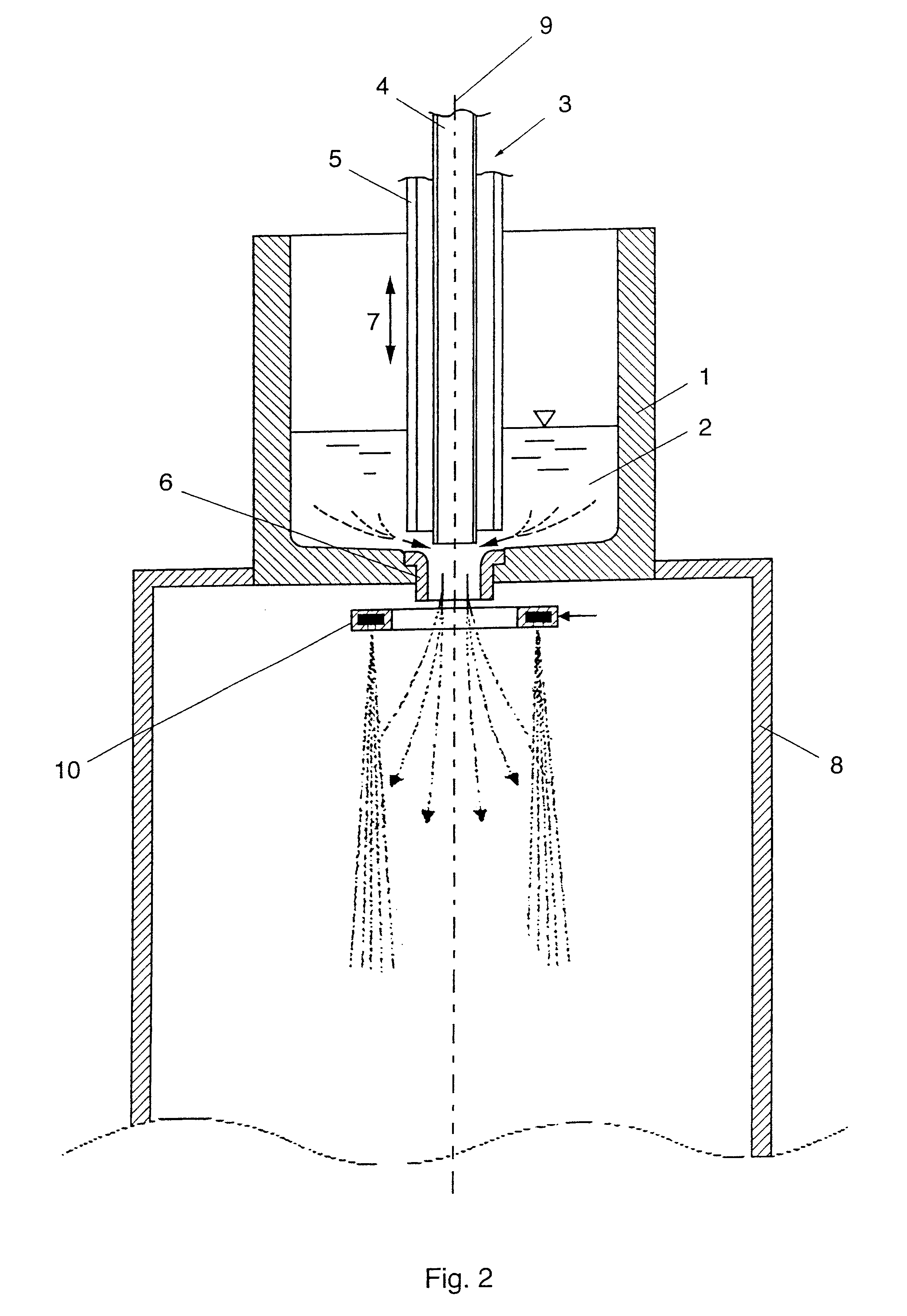
As already pointed out in the beginning, it is particularly advantageous if the geometry of the outlet opening is kept free of influences such as, for instance, closing up by solidification, and it, therefore, corresponds to a preferred embodiment that the nozzle block and the external tube or sleeve are connected with a power source to provide electrical heating in the region of the nozzle block.

