Optical transmitter and anamorphic lens therefor

an optical transmitter and anamorphic technology, applied in the field of optical transmitters and anamorphic lenses therefor, can solve the problems of hence the effective device output power, reducing the overall device output power and efficiency of the overall device, and reducing the coupling efficiency, so as to minimise wave front distortion, optimise lens design, and efficient coupling of laser radiation

Inactive Publication Date: 2003-12-09
NORTEL NETWORKS LTD
View PDF1 Cites 11 Cited by
  • Summary
  • Abstract
  • Description
  • Claims
  • Application Information

AI Technical Summary

Benefits of technology

A further object of the invention is to provide an improved anamorphic lens construction.
According to another aspect of the invention there is provided a method of fabricating an anamorphic lens having first and second cylindrical surfaces having mutually perpendicular planes of symmetry, wherein each said surface is defined from a generator polynomial including cross terms in first and second independent variables so as to correct aberration of light from a widely divergent source, the method comprising: generating a trial design, and selectively adjusting coefficients in the polynomial corresponding to that trial design so as to optimise the lens design so as to provide a minimised wave front distortion.
In another aspect, the invention provides an improved anamorphic lens design for the efficient coupling of laser radiation from optoelectronic devices into optical fibres and other waveguide devices. More particularly, the lens manipulates the highly elliptical beam produced by high power laser sources to produce an almost circular parallel beam suitable for efficient coupling into optical fibres and other waveguide devices. The configuration of the lens surfaces is designed to minimise aberration.

Problems solved by technology

There is considerable commercial pressure to maximise the overall device output power and efficiency.
Unfortunately, high power laser sources tend to produce highly elliptical beam and highly divergent shapes which, for the reasons discussed below, substantially reduce the coupling efficiency and hence the effective device output power.
In particular, it has been found that the high power lasers now becoming available have such a high degree of beam divergence and ellipticity that this cannot be fully corrected by the use of conventional anamorphic lenses.
This is a particular problem as high beam ellipticity substantially reduces the coupling efficiency of the laser output into a circular fibre.
Lack of overlap between the elliptical laser beam and the fibre mode reduces the coupling efficiency.
However, it has been found that the above designs only provide effective aberration correction along the x and y axes.
For these designs, the current anamorphic lens design will no longer be effectively aberration free.
Although current lens designs can correct aberration in the horizontal and vertical planes, they are, when presented with a highly divergent elliptical beam, significantly less effective in the correction of aberration in the planes at 45.degree. to the horizontal and vertical planes.

Method used


Image

  • Optical transmitter and anamorphic lens therefor
  • Optical transmitter and anamorphic lens therefor
  • Optical transmitter and anamorphic lens therefor

Examples


Embodiment Construction

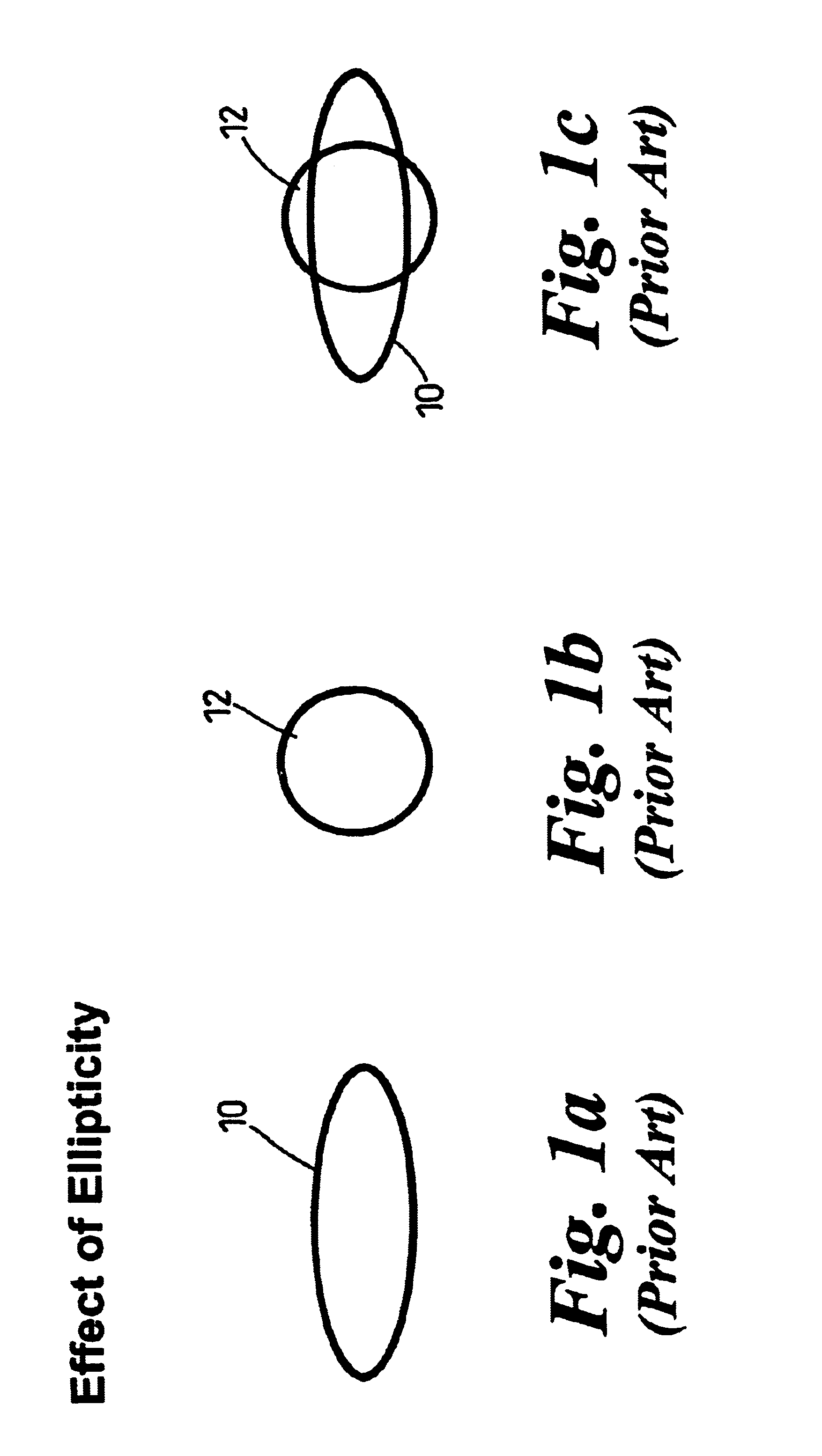
FIGS. 1a to 1c have been discussed above and are included for comparative and explanatory purposes.

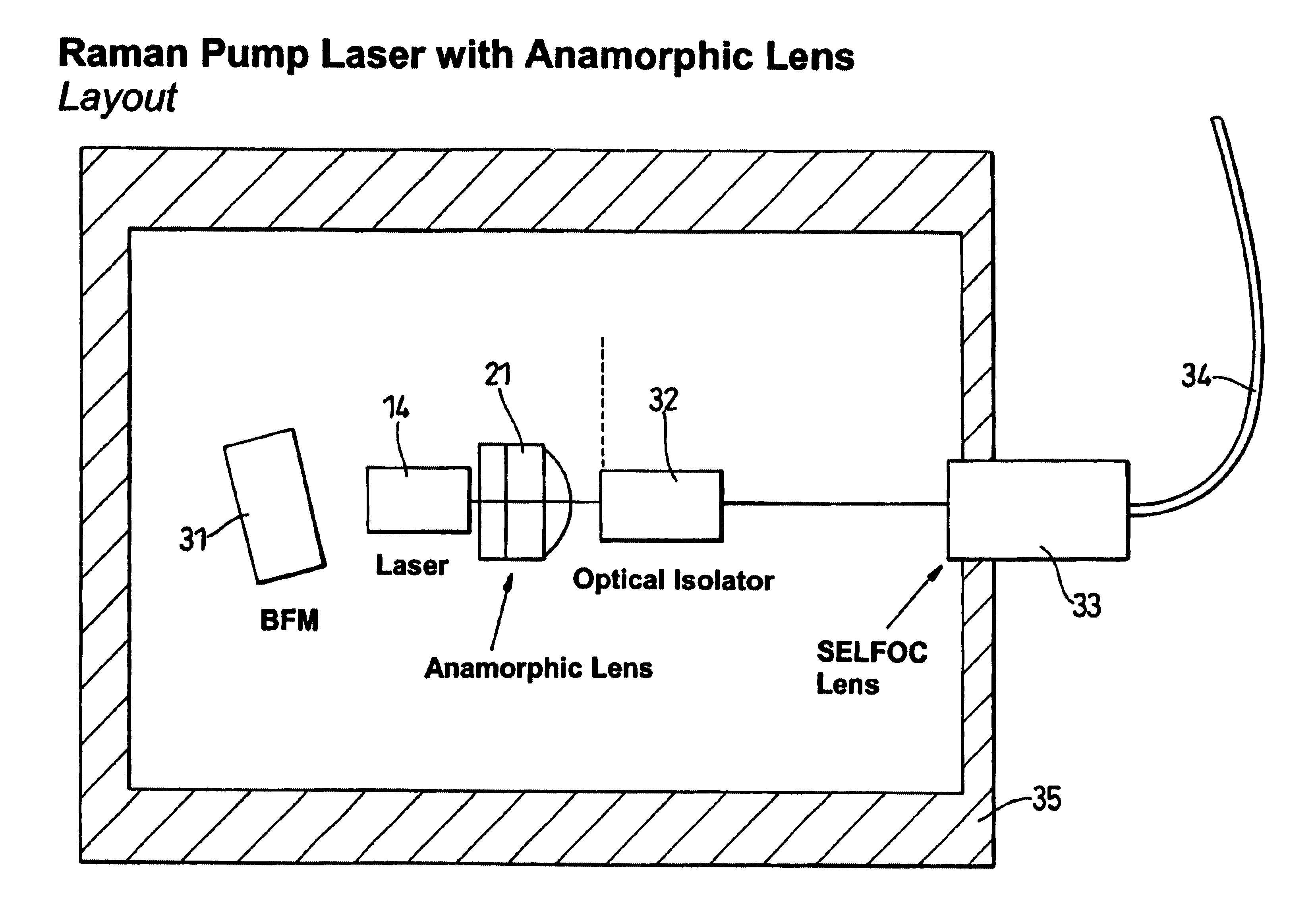
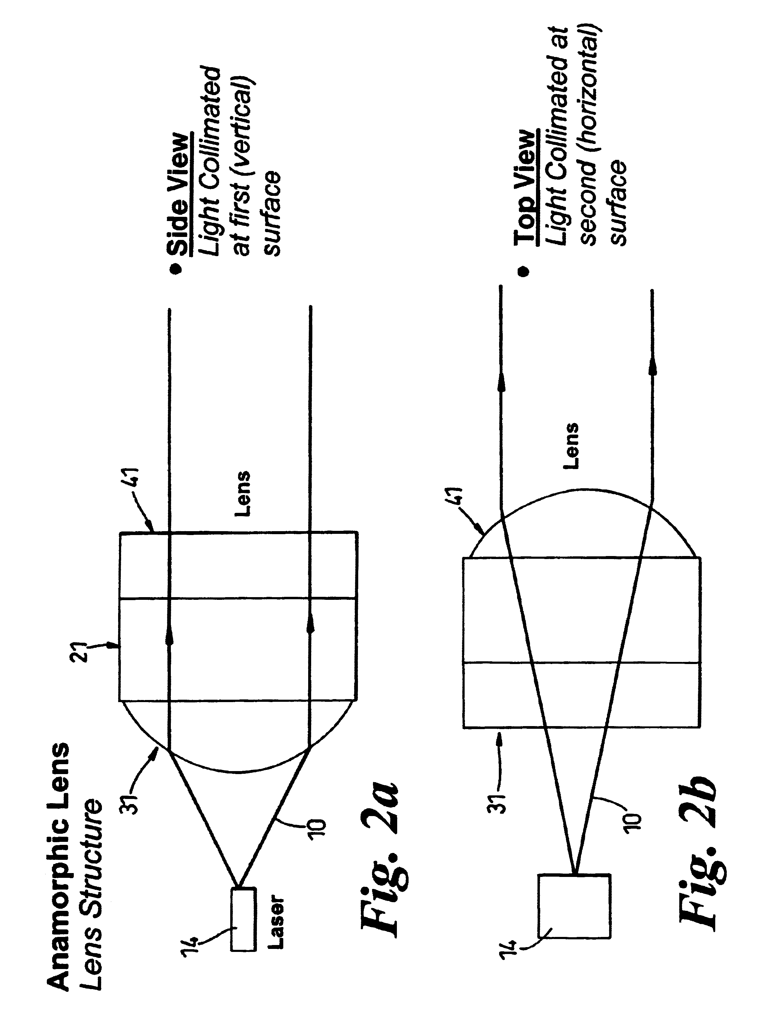
Referring now to FIGS. 2a and 2b, these figures together show the construction of the anamorphic lens. The general form of the lens 21 is that of two crossed, non-circular, cylindrical surfaces 31, 41 (referred to as the x and y surfaces). The diagram above shows a side view and a top view. The side view of FIG. 2a illustrates the collimation in the vertical plane of the elliptical beam 10, output from the laser 14 by the first cylindrical surface 31 (the x surface). The second surface 41 (the y surface) is oriented at 90 degrees to the x surface and provides collimation in the horizontal plane.

Each of the cylindrical surfaces 31, 41 is defined by a respective polynomial expression. In addition to the terms in powers of x and y, this polynomial also incorporates `cross terms` in x and y. The inclusion of these cross terms in the generating polynomial has been found to provide correctio...


PUM


Abstract

An anamorphic lens for correcting aberration of a highly divergent beam from a laser source has first and second cylindrical surfaces having mutually perpendicular planes of symmetry. Each surface is defined from a generator polynomial including cross terms in two variables so as to correct aberration of light from a widely divergent source. Preferably, the generator polynomial is of the formThe coefficients in this polynomial may be determined by the use of ray tracing software. The lens may be employed as a collimating lens in an optical transmitter e.g. for use in an amplifier package.

Description

This invention relates to optical transmitters for use in communications systems, and to anamorphic lenses for use in such transmitters.The bandwidth explosion driven by Internet usage has created a demand for an adaptable, high performance optical network. One of the key technologies in delivering high performance over a long haul network is pump laser technology, particularly Raman Laser technology. From a market perspective, device output power is the most important performance characteristic of such devices. There is considerable commercial pressure to maximise the overall device output power and efficiency. It is of course an advantage to operate at high laser powers as this can increase the spacing between amplifier stations in an amplified system and thus provide a significant cost reduction. Unfortunately, high power laser sources tend to produce highly elliptical beam and highly divergent shapes which, for the reasons discussed below, substantially reduce the coupling effic...

Claims


Application Information

Patent Timeline
Patent Type & Authority Patents(United States)
IPC IPC(8): G02B27/09G02B13/08G02B3/02G02B3/06
CPCG02B3/06G02B13/08G02B19/0014G02B27/0955G02B19/0052G02B27/09
Inventor ROLT, STEPHEN
Owner NORTEL NETWORKS LTD
Why Eureka
Try Eureka