Rail mounted traversing transport

a technology of rails and platforms, applied in the direction of rope railways, locomotives, ways, etc., can solve the problems of reducing the affordability of lake lot vacation or residential homes for all but the wealthy, deemed undesirable or even undevelopable, and the vast majority of property bordering lakes is undeveloped, etc., to achieve the effect of increasing the attractiveness of the entire surrounding area, reducing the cost of lake lot vacation or residential homes, and increasing the weight on the platform

Inactive Publication Date: 2003-12-23
INCLINE ACCESS
View PDF27 Cites 27 Cited by
  • Summary
  • Abstract
  • Description
  • Claims
  • Application Information

AI Technical Summary

Benefits of technology

The present invention may be described basically as a self leveling transport device with application for delivering people and their accessories between an elevated lake lot and the water line. The transport may be adapted to be low profile against the silhouette of a land slope, increasing attractiveness of the entire surrounding area. The device is able to adjust the "attitude" of a load or platform by selectively leveling, or causing to be off level, the load or platform (relative to a horizontal plane, the ground, or other selected orientation or parameter).
Unlike previous rail-mounted systems, the current invention does not require either a constant slope of the incline, or a mechanico-electrical leveling-adjustment system. Rather, within reasonable limits, the rail may be run, if desired, in a straight line (viewed from the water) from the top of an incline to the bottom, hugging the contour of the earth surface the entire distance. This lowers the dangers associated with elevated portions of track that may become necessary for maintaining a constant slope in prior art systems.
The present invention employs a support body platform (which may be a floor bucket, chair, or any other supporting or holding device, including pinchers) connected to a rail by wheels or other traversing members, such as wheels, rollers, bearings, tracks, skids (particularly low-friction skids). One traversing member contacts the rail from below, and a second traversing member contacts the rail from above. Typically, this places the second traversing member both horizontally and vertically offset from and above the first traversing member, when viewed from the side. The platform is connected to the second traversing member and extends over the downslope side of the rail. This creates a cantilevered, or torqued design, in which the center of gravity of the loaded platform is on the opposite side of the second traversing member from the first traversing member, and in which the platform is above the level of the rail. Accordingly, as weight on the platform is increased, the torque increases the effectiveness of friction between traversing members and rail. The present invention can therefore in some embodiments rely wholly upon friction of the traversing members to maintain location upon the rail within preferred operational parameters. The system is therefore amenable to cableless direct drive operation in embodiments using wheels or tracks at the traversing members, in contrast to many prior art devices.
It should be noted that the location of the center of gravity of the platform may change in various states of loading or unloading; it is possible to take advantage of such change by allowing for a shift of the center of gravity to the opposite side of the second traversing member, allowing for easy removal of the platform, maintenance of the traversing members or other equipment, storage, etc.
In order to achieve reliable and durable self-leveling, neither the traversing members nor the angle among the traversing members and the platform needs to be variable; rather each of these can be hard-welded or secured in any other static fashion. Self leveling is effected in the present invention by varying the vertical gauge of the rail (by "vertical gauge," or "gauge" hereinafter, is meant the distance from a point on the upper surface of the rail to the closest point on the undersurface of the rail). At any given distance between the traversing members, the cantilever effect causes a wider gauge rail to urge the line between the traversing members to approach perpendicular to the top of the rail. A thinner gauge rail will allow the line between the traversing members to pivot away from perpendicular to the rail, towards an angle that is limited in its acuteness by the configuration of the traversing members (e.g., where wheels are employed as the traversing member, the radial height of the wheels will affect the acuteness of angle obtainable) and the gauge of the rail. Accordingly, the user can determine from the minimum desired gauge of the rail and the configuration (e.g., minimum radius of wheels) of the traversing members, how far off of parallel the line between the traversing members will be from the rail at its most horizontal point. The platform can thereafter be attached to the traversing members in such a way that the fixed angle among the traversing members and the platform results in a horizontally level platform at the most horizontal point on the rail. As the rail becomes more vertically disposed traveling along its length, the platform may be maintained at a horizontal level by widening the gauge of the rail, which will drive the line--and thus the platform--into a changing relationship with the rail to compensate for the increasing slope.
The present invention overcomes the chief limitations of static slope requirement systems, while avoiding complex linkages and mechanical systems.

Problems solved by technology

Water-level lake lots are available for purchase with increasing rarity, and at increasingly inflated prices, substantially reducing the affordability of lake lot vacation or residential homes for all but the wealthy.
At the same time, the vast majority of property bordering lakes is undeveloped and has heretofore in many cases been deemed undesirable or even undevelopable because of the grade or obstacles present between the waterline and a suitable location for building a house.
The difficulties associated with getting to the focal point of such lots--the water--typically prevent the lot from being maximized as a leisure area, or from ever being useable at all for persons with special needs.
Numerous solutions have been advanced to address this problem, none of which are entirely acceptable.
Such solutions range from the traditional winding stairs, which can be exhausting or even dangerous for the elderly, infants, and those with special needs, to typically traction cable-lift transport designs.
Even these mechanical transports are limited in their application, being by their nature confined to either of two models: (1) a constant slope incline model, or (2) mechanically leveled models that involve moving linkages and machinery to maintain the surface of a transport platform at a relatively level position.
Additionally, as the slope of the rails is not dependent upon any external factors, Redford shows a constant slope for the rails and includes no leveling mechanism; the teaching of Redford is therefore limited to extremely narrow applications.
Redford's device is cable driven and therefore subject to heightened maintenance and safety concerns of such cable systems.
The typical hanging load system requires the weight to be centered on the platform; otherwise, the stability and consistency of leveling will be suspect.
These systems are subject to undesirable swaying motion, particularly at sudden starts and stops.
Other developers have noted difficulty with obtaining reliable and consistent grip between the rails of a transport and the wheels when on a slope.
None of these prior art systems has maximized the potential available for reliable self leveling traversing devices.
It further will be noted by those reasonably skilled in the art that the more complex the leveling, gripping, or safety system becomes, the greater the number of practical issues that arise, such as the expense of manufacture of additional components and the fact that additional components increase the potential for unacceptable failure.

Method used


Image

  • Rail mounted traversing transport
  • Rail mounted traversing transport
  • Rail mounted traversing transport

Examples


Embodiment Construction

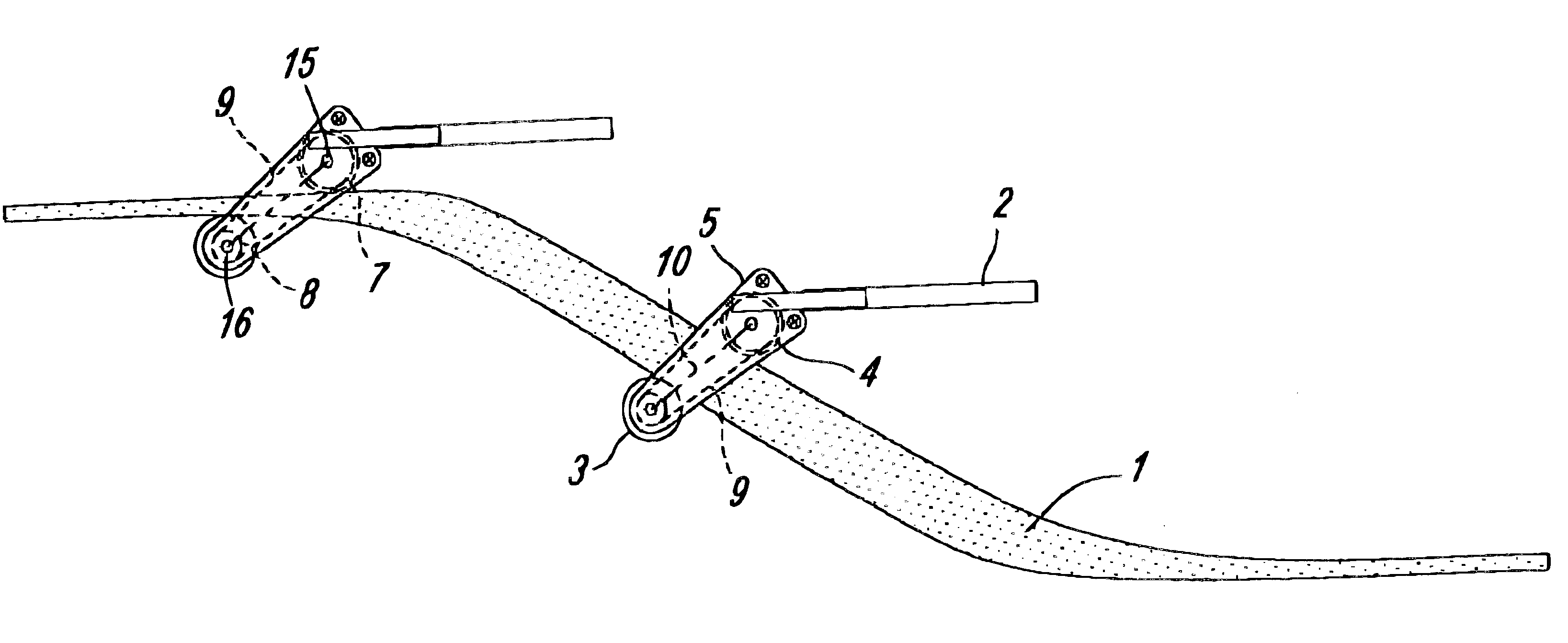
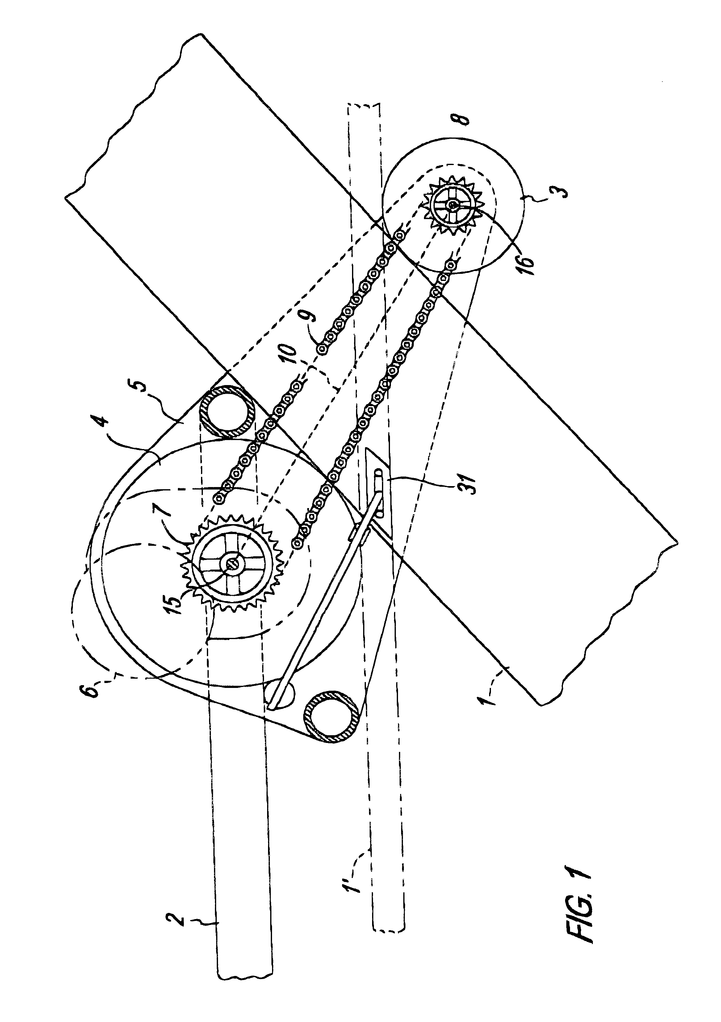
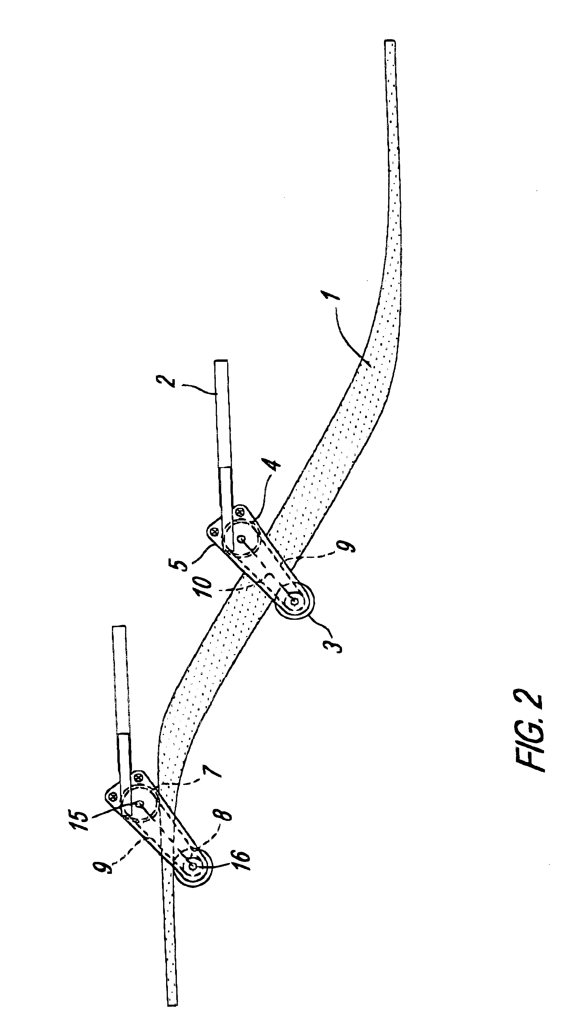
. Those skilled in the art will understand that the specificity provided herein is intended for illustrative purposes with respect to the inventor's preferred and most preferred embodiments, and is not to be interpreted as limiting the scope of the invention. It must be understood without limitation that the term "rail" as used herein encompasses such variants of rails as may be substitutable for rails, such as tracks, beams, planks, pipes, runners, or other weight-bearing guidance configurations; additionally, within the meaning of "rail," a single rail or two separate rails may be used to present an upper surface for meeting the downward component of torque or cantilever forces and a lower surface to meet the upward component of torque or cantilever forces. Furthermore, although these embodiments tend to show wheels as the selected traversing members, it must be understood that other traversing members will work equally well within the scope of the invention. As such, in the follo...


PUM


Abstract

A transportation system is provided that accommodates varying angles of slope along the path of its movement, while maintaining a level transportation platform without the need of mechanical leveling devices or systems. The platform may be connected to the rail by wheels, the closest of which to the platform is above the rail, and the other below the rail. Accordingly, the platform is torqued downward to maintain contact between the wheels and the rail. As the slope of the terrain, and thus the rail, increases, the rail is widened to maintain the platform at level. As the slope decreases, the rail is narrowed to the same effect. The platform also may be tilted for loading or unloading by this rail-widening method, as may be desired.

Description

1. Field of the InventionThis invention relates generally to solutions for moving people or items from one location to a higher or lower location along a variable slope without the need for complex leveling mechanisms. More particularly, the invention is directed toward outdoor transportation devices for moving people and things between elevated lake lots and the waterline in a safe and efficient manner along an incline that may vary substantially in slope.2. Description of Related ArtWater-level lake lots are available for purchase with increasing rarity, and at increasingly inflated prices, substantially reducing the affordability of lake lot vacation or residential homes for all but the wealthy. At the same time, the vast majority of property bordering lakes is undeveloped and has heretofore in many cases been deemed undesirable or even undevelopable because of the grade or obstacles present between the waterline and a suitable location for building a house. The difficulties asso...

Claims


Application Information

Patent Timeline
Patent Type & Authority Patents(United States)
IPC IPC(8): B61B7/00B61B7/06B66B9/06B66B9/08
CPCB61B7/06B66B9/0838B61B13/06
Inventor MINGES, MARCUS C.
Owner INCLINE ACCESS
Why Eureka
Try Eureka