Slide in, hook and fold out ceiling fan blades

Inactive Publication Date: 2003-12-23
CHIEN LUEN INDS
View PDF26 Cites 28 Cited by
  • Summary
  • Abstract
  • Description
  • Claims
  • Application Information

AI Technical Summary

Benefits of technology

A first objective of the subject invention is to provide ceiling fan blades that can be easily and quickly attached onto a ceiling fan mounted motor without the need of using removable fasteners such as screws and the like.
A fourth embodiment can be used with the third embodiment and allows for a spring type clip to further lock the blade to the ceiling fan motor. The clip can be pre-attached for example, to the medallion portion and when the blade and medallion are folded downward can expand about and contact against or about portions of the arm, the hinge portion on the arm, and the like. The clip can also restrict lateral and or vertical movement between the blade and the ceiling fan motor. The clip can be used with one or more posts, and with or without any vibration and noise type resilient members.

Problems solved by technology

For example, ceiling fan blades are generally shipped in detached positions and are fastened onto the motors and ceiling fan arms by screw type fasteners during the assembly process, a practice having many inherent problems.
Clearly, problems occur when any of this small screw type fasteners become lost and / or missing during the assembly process.
In addition to having multiple loose parts, a typical installer must follow a tedious process in order to assemble and hang the ceiling fan.
This final assembly step takes great dexterity, patience, balance and time for the installer.
This tedious traditional process of assembly and installation causes many potential problems.
First, the screw type fasteners can and do accidentally fall and become lost causing more time and expense to finish the installation.
Also, the blade 30 and mounting arm 40 have been known to fall on and cause injury to the installer 60 during assembly.
Furthermore, the installer can lose their balance and injure themselves by falling off the ladder or stool.
The use of screws has other inherent problems as to their appearance.
Visible screws are unsightly and further detract from the appearance of the ceiling fan itself.
Still additional problems have been known to occur after installation of the screw type fasteners.
For example, uneven tightening of each of the plural screw type fasteners that connect the blades to the mounting arms has resulted in wobble effects when the ceiling fan is running.
Another problem occurs as a result of the need to clean blades over time in order to remove dirt and dust buildup.
Furthermore, this messy cleaning operation with brushes while the blades are attached to the ceiling fan mounted motor often results in dirt and debris falling on both the cleaner and furniture and flooring below the ceiling fan.
Another problem occurs when the ceiling fan is taken down to be reboxed.
In order to be repackaged, each and every component must be disassembled, a time consuming endeavor, which also can result in many loose parts becoming misplaced and lost over time.
A still another problem with blades having removable fasteners includes inherent problems with vibrations and noise that result from the spinning blades.
However, the embodiments generally require some screw type fasteners be used that still would have many of the problems described above.
Besides the wobble and rattle problems, each time the ceiling fan stops the hooked on blades can potentially fall off and become damaged as well as injure those beneath the ceiling fan.
Similarly the "pin" supported blades of FIG. 5F would also wobble and rattle for not being properly secured to the mounting arms.
In addition, these "pins" can inherently become loose and cause the blades to possibly fall off, become damaged and possibly injure those beneath the ceiling fan.
Furthermore, the Hodgkins '486 reference fails to take into account the inherent vibration and noise problems that can result when using fasteners such as screws, and the like.
Additionally, other embodiments in this reference allow some parts to directly contact one another, such as metal arms directly contacting metal blades, and the like, which would result in undesirable vibration and noise.

Method used


Image

  • Slide in, hook and fold out ceiling fan blades
  • Slide in, hook and fold out ceiling fan blades
  • Slide in, hook and fold out ceiling fan blades

Examples


first embodiment

This invention is further related to U.S. Pat. No. 6,010,306 to Bucher et al. and U.S. Pat. No. 6,171,059 to Bucher et al.; and U.S. Pat. No. 6,213,716 to Bucher et al., each having the same inventors and assignee as the subject invention and each being incorporated by reference.

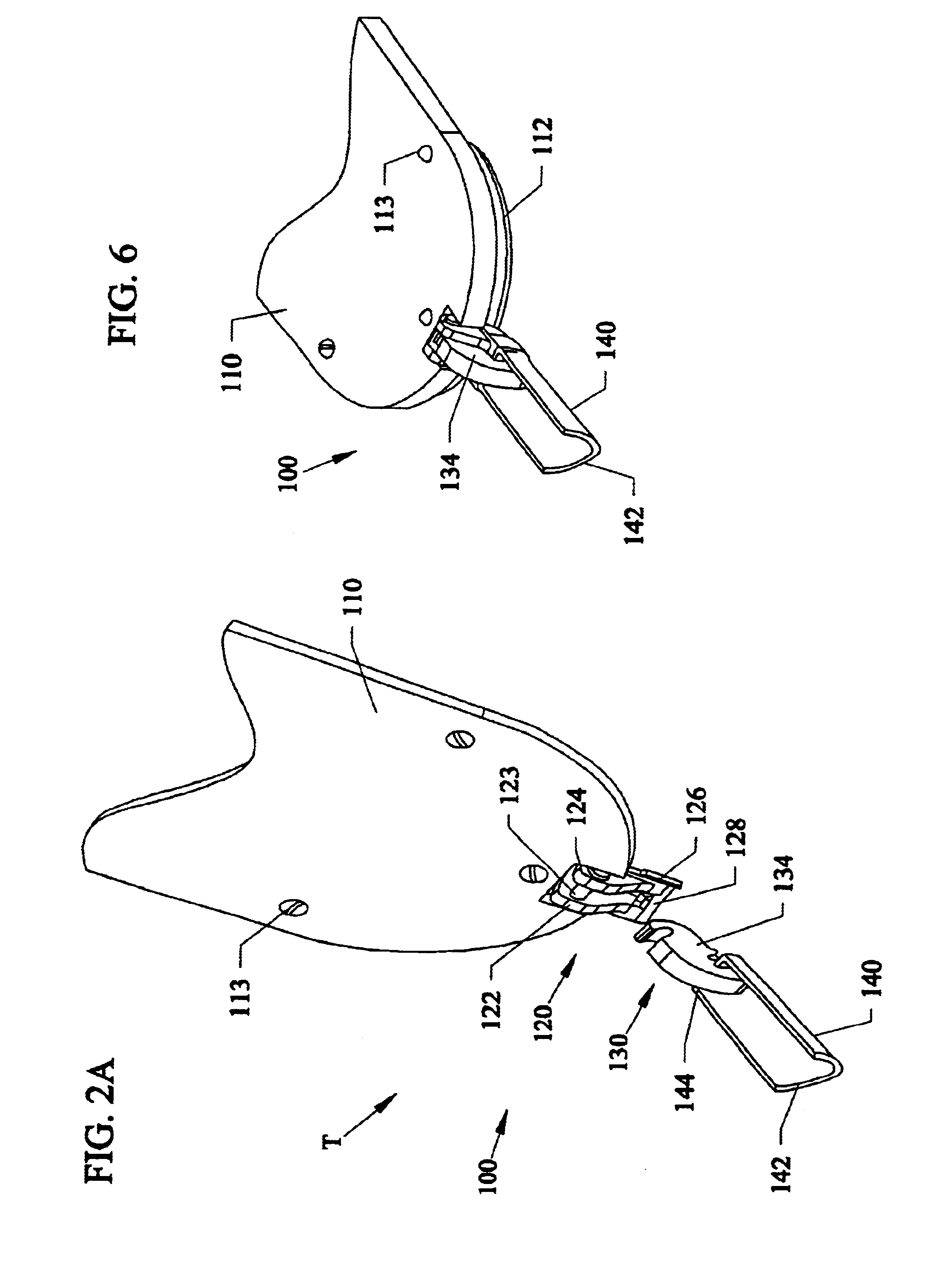
FIG. 2A is a perspective view of a first embodiment 100 of the hook and fold ceiling fan blade with a blade 110 ready to be attached to a motor / arm 140. FIG. 2B is a top view of FIG. 2A along arrow T. FIG. 2C is a side cross-sectional view of FIG. 2B along arrows A--A. Referring to FIGS. 2A-2C, ceiling fan blade 110 can have a medallion cover 112, attached thereon with fasteners 112, such as screws, and the like. Attached to the medallion 112 can be a connector section 120 having two raised wall type members 122, 124 with a pin member 123 connected attached therebetween. The bottom of connector 120 has an upper bottom surface 126, which steps down at 127 to a lower bottom surface 128. A raised ridge type mem...

second embodiment

A second embodiment of the subject invention hook and lock blades will be described in reference to FIGS. 7A-14D. FIG. 7A is a perspective view of a second embodiment 200 of the hook and fold ceiling fan blade invention with the blade 210 ready to be attached to a motor / arm 240. FIG. 7B is a top view of FIG. 7A along arrow S. FIG. 7C is a side cross-sectional view of FIG. 7B along arrows B--B.

FIG. 12A is a perspective view of the lower medallion cover 212B of the second embodiment 200. FIG. 12B is a top view of the cover 212B of FIG. 12A along arrow X1. FIG. 12C is a side view of the cover 212B of FIG. 12B along arrow X2. Referring to FIGS. 12A-12C, medallion cover 212B can include two arms 222 and 224 attached to and extending from a rear portion so that a rotation pin 223 can be fixably inserted into mounting holes 221, 225 so that pin 223 can be fixably attached to both arms 222 and 224.

FIG. 13A is a perspective view of the upper medallion cover 212A of FIGS. 7A-11 without pin su...

third embodiment

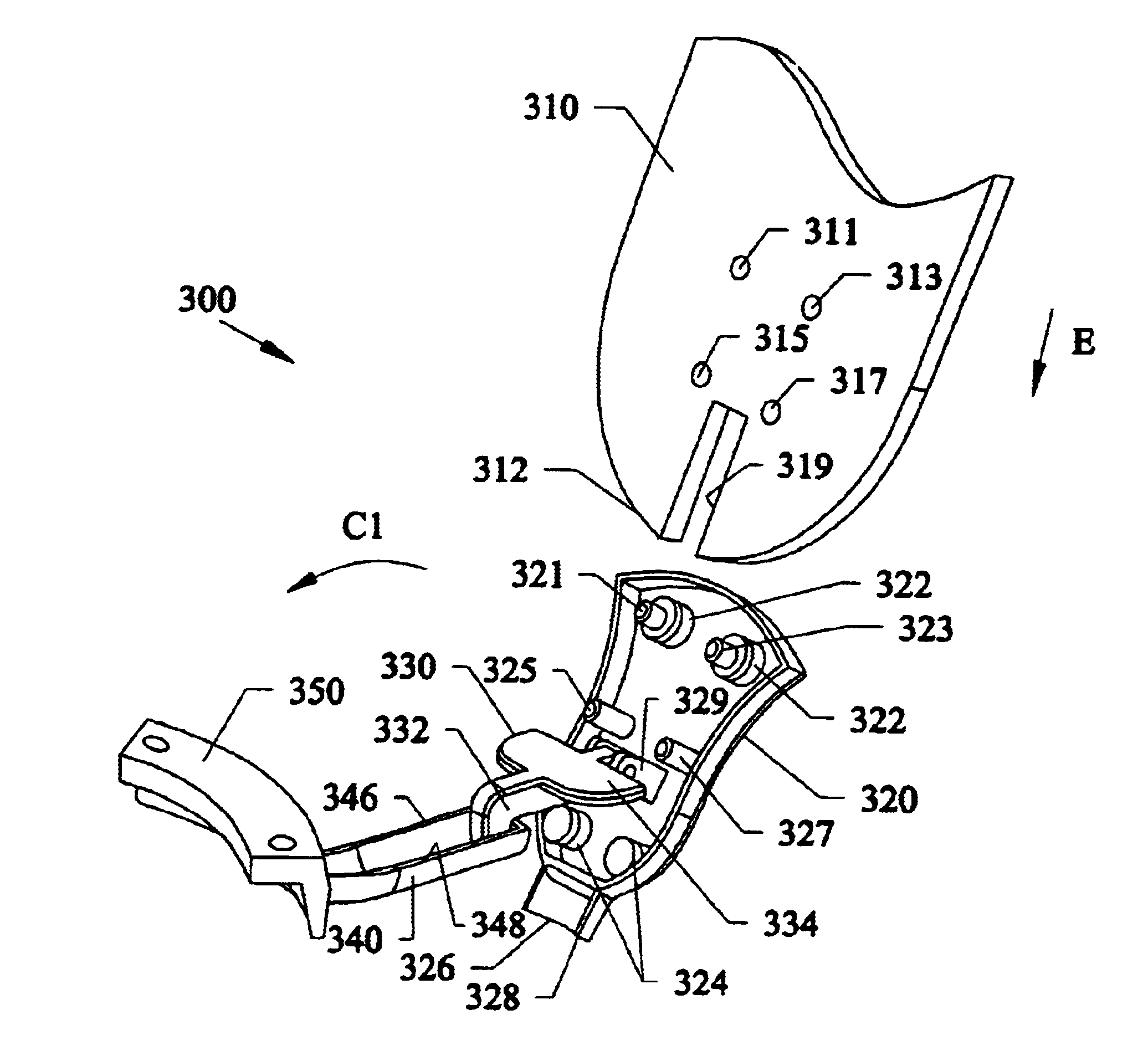
The third embodiment allows for less assembly steps by allowing for the blade(s) to be pre-installed onto the arm(s) 340 or the motor at a factory, and in the bent position shown in FIG. 17 be further bent so that the blade(s) 310 are at a substantial ninety degree bent angle and packaged in a way similar to that shown and described in U.S. Pat. No. 6,213,716 to the same inventors and assignee as the subject invention, which is incorporated by reference. Also, the blade(s) 310 could be packed separated from the arm(s) 340 and / or fan motor in a packing box such as done in many conventional ceiling fan packages.

Fourth Embodiment

FIG. 19A is an exploded perspective view of a fourth embodiment 400 of a medallion 420 and spring clip 460. FIG. 19B is another perspective view of FIG. 19A with spring clip 460 attached to the medallion 420.

Similar to the medallion 320 of the third embodiment, the fourth embodiment medallion 420 can include at post type member(s) 421, 423. Hinge post(s) 429 ar...


PUM


Abstract

Slide in, hook on and lock blades for ceiling fans having vibration and noise reduction through resilient members. A mount attached to the motor can be bendable by a hinge so a raised portion can receive a slot on the blade. The mount has a post where a blade can be hooked. Folding the blade locks the blade substantially eliminating lateral and vertical movement of the blade and can also eliminate vibration and noise. A clip can be used to lock the blade or eliminate lateral and / or vertical movements. An expandable and contracting clip can hold the blade and can be used with a post or posts, and can quickly allow the blade to be snapped into place. The invention allows centrifugal forces and / or the overall weight of the blades(by gravity) to hold the blades.

Description

BACKGROUND AND PRIOR ARTConventional ceiling fans that are shipped in cartons have separate packing materials such as foam inserts for the many components that must be assembled by the installer to hang the ceiling fan. For example, ceiling fan blades are generally shipped in detached positions and are fastened onto the motors and ceiling fan arms by screw type fasteners during the assembly process, a practice having many inherent problems.A single conventional ceiling fan blade has often required some five screw type fasteners to attach the blade to the motor / arm of the ceiling fan. Thus, a five blade ceiling fan can have some twenty five screw type fasteners just for attaching the fan blades to the motor and arm assembly. Clearly, problems occur when any of this small screw type fasteners become lost and / or missing during the assembly process.In addition to having multiple loose parts, a typical installer must follow a tedious process in order to assemble and hang the ceiling fan....

Claims


Application Information

Patent Timeline
IPC IPC(8): F04D25/08F04D25/02F04D29/34F04D29/32
CPCF04D29/34F04D25/088
Inventor BUCHER, CHARLES E.BUCHER, JOHN C.
Owner CHIEN LUEN INDS
Why Eureka
Try Eureka