Lever handle support mechanism

a technology of lever handle and support mechanism, which is applied in the direction of wing knobs, carpet fasteners, mechanical devices, etc., can solve the problems of affecting the desired function of the lock, the appearance of a drooping handle is visually undesirable, and the opposite lever handle to droop, etc., and achieves the effect of being cheap to manufactur

Inactive Publication Date: 2003-12-30
SARGENT MANUFACTURING CO INC
View PDF15 Cites 18 Cited by
  • Summary
  • Abstract
  • Description
  • Claims
  • Application Information

AI Technical Summary

Benefits of technology

is to provide a handle support mechanism that is relatively inexpensive to manufacture.

Problems solved by technology

However, when lever handles are used, compression of the common spring return mechanism, by rotation of one lever handle, causes the opposite lever handle to droop.
The appearance of a drooping handle is visually undesirable.
Moreover, in some applications this drooping motion of the unused handle interferes with the desired function of the lock.
However, when lever handles are installed in a switch-monitored mortise lock of this type, the drooping motion of the unused lever handle causes both switches to operate when either handle is used.
The problem also occasionally occurs with round doorknobs in mortise lock designs that frictionally transmit some of the rotational force from the operated handle to the non-operated handle.
Although a redesign of the mortise lock mechanism to incorporate additional springs in the mortise case may solve this problem, such redesign is expensive and is not warranted for the limited number of applications where handle droop during operation of the opposite handle is a problem.

Method used


Image

  • Lever handle support mechanism
  • Lever handle support mechanism
  • Lever handle support mechanism

Examples


Embodiment Construction

)

In describing the preferred embodiment of the present invention, reference will be made herein to FIGS. 1-11 of the drawings in which like numerals refer to like features of the invention.

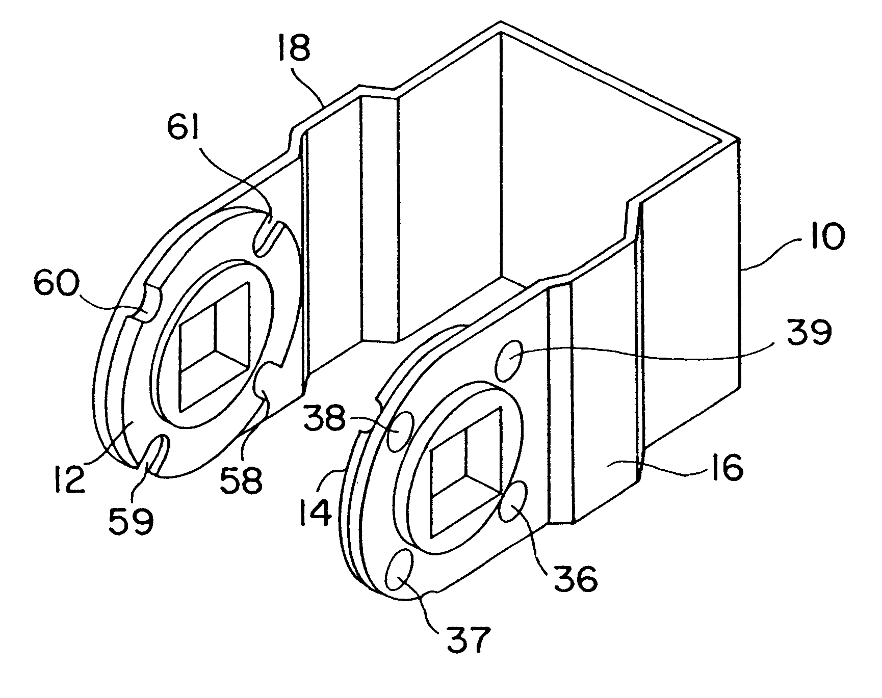
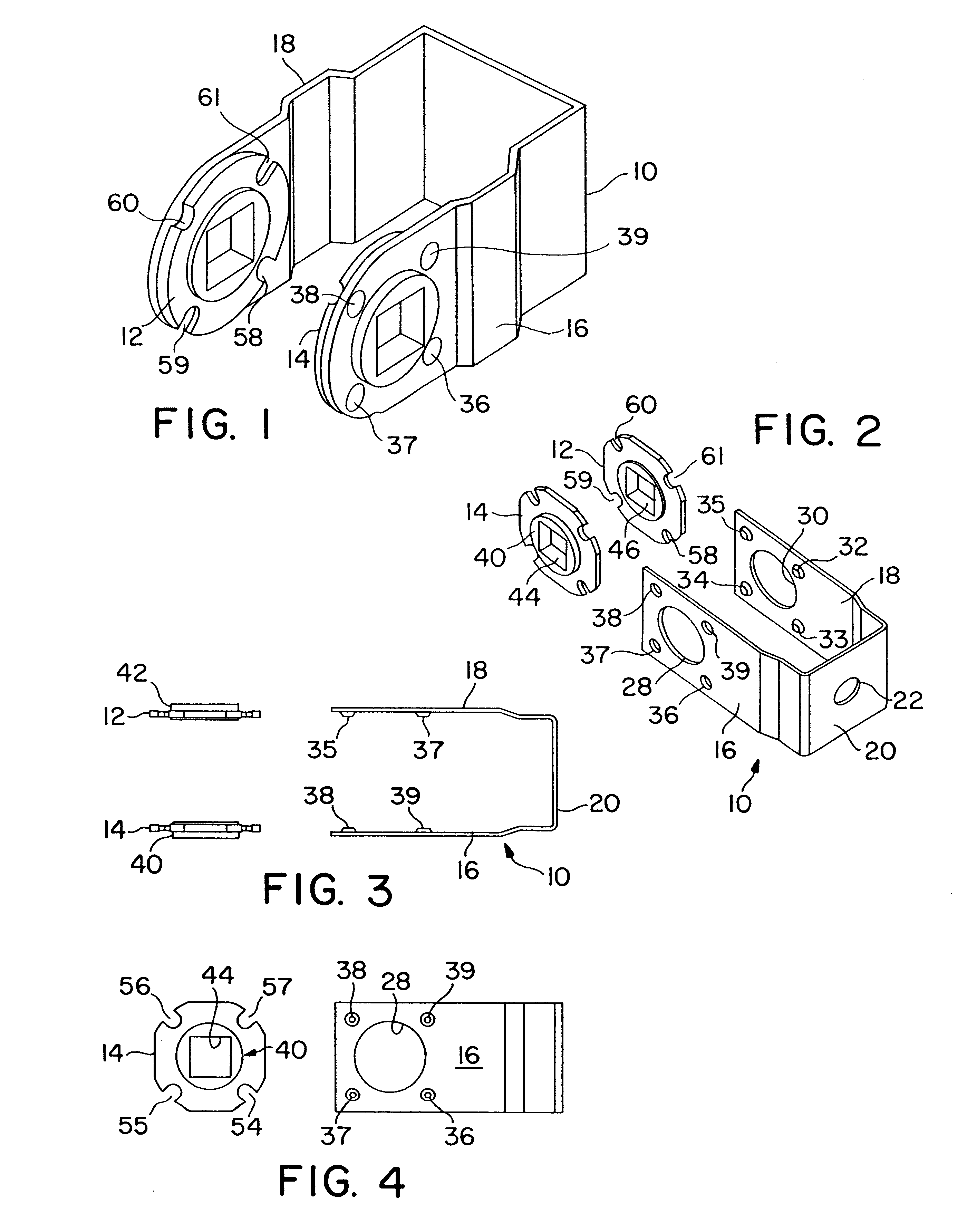
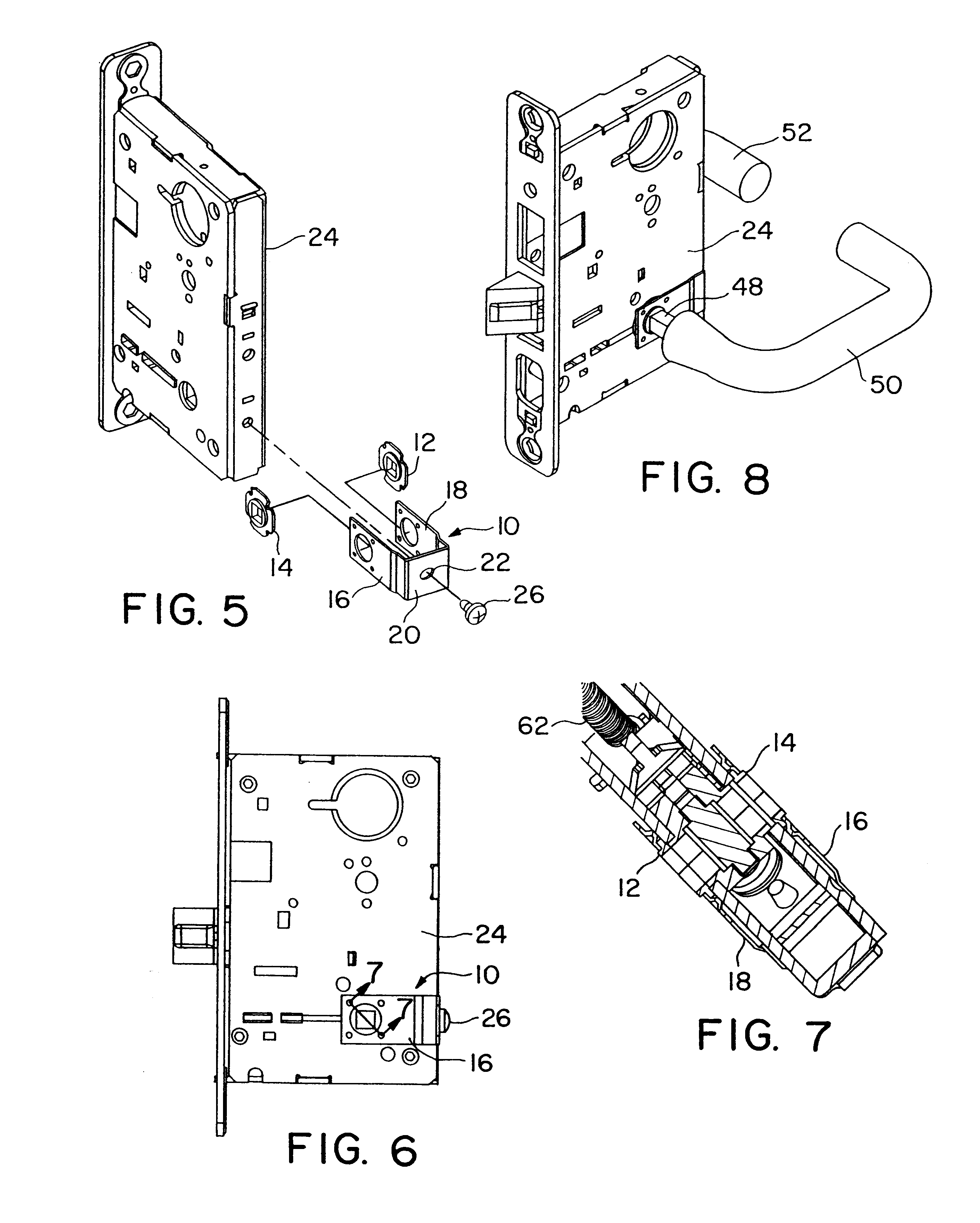
FIG. 1 shows a first embodiment of the present invention and FIGS. 2-4 show a second embodiment of the invention. FIGS. 5-11 use the embodiment of FIGS. 2-4 to illustrate how the invention is attached to a conventional mortise lock. The two embodiments function in substantially the same way and are attached to a mortise lock in the same manner. Consequently, the same reference numbers are used in connection with both embodiments of the invention. The embodiments in FIGS. 1 and 2 differ only in the shape of the corners, the bends in the spring bracket 10 and the elimination of mounting hole 22. With mounting hole 22 eliminated, the spring bracket 10 is self-supporting and floats on handle spindles 48, 49 (see FIG. 8), as described below.

The invention includes a U-shaped spring bracket 10 and a pair...


PUM


Abstract

A handle support mechanism is designed for attachment to a door lock, preferably the exterior of a mortise lock, that has two handles driven back to an initial position with a common return spring after either handle is used. The support mechanism prevents the unused handle from drooping or rotating when the common return spring is compressed as the opposite handle is turned. The support mechanism includes first and second friction discs trapped between the exterior of the mortise lock and the legs of a U-shaped spring bracket. The spring bracket applies an inward spring pressure to prevent a friction disc and its corresponding handle from turning when the other handle is in use. The handle support mechanism improves visual appearance and is particularly suitable for retrofit installations, lever handle designs and mortise locks with independent switch sensors on the two handles that notify a monitoring system as to which handle was turned to open a monitored door.

Description

1. Field of the InventionThe present invention relates to mortise locks equipped with lever handles. More particularly, the present invention relates to mortise locks where inner and outer lever handles are held level by a common spring return mechanism and where it is necessary to support one handle in the level position while the opposite handle is being operated against the pressure of the common spring return.2. Description of Related ArtA mortise lock is operated by inner and outer handles located on opposite sides of the mortise lock case and typically includes a spring return mechanism that returns a handle to its initial position after it is rotated. Provided the mortise lock is in the unlocked state, rotation of either handle will retract the latch bolt, compress the spring return and open the door. When the rotated handle is released, the spring return mechanism returns the handle to its original position.In a conventional mortise lock design, the inner and outer handles a...

Claims


Application Information

Patent Timeline
Patent Type & Authority Patents(United States)
IPC IPC(8): E05B63/00E05B63/16E05B15/04E05B15/00E05B47/00
CPCE05B9/02E05B15/0053E05B63/16E05B15/0013Y10S292/53E05B2047/0067E05B15/04Y10T292/62Y10T292/82Y10T292/854
Inventor HUANG, RICHARD HAINUNEZ, PAUL
Owner SARGENT MANUFACTURING CO INC
Why Eureka
Try Eureka