Power source and arrangement for restricting the short-circuit current or rectifier

a short-circuit current or rectifier technology, applied in the direction of electric variable regulation, process and machine control, instruments, etc., can solve the problems of large short-circuit current in the output conductor, damage to components and even circuit boards, and the power required by diodes

Inactive Publication Date: 2003-12-30
NOKIA SOLUTIONS & NETWORKS OY
View PDF6 Cites 47 Cited by
  • Summary
  • Abstract
  • Description
  • Claims
  • Application Information

AI Technical Summary

Benefits of technology

is to provide a power source and method for restricting a short-circuit current, which power source comprises a primary-side switch block, transformer unit and a rectifier which includes at least one switching transistor.

Problems solved by technology

A problem with diode rectifiers of galvanically isolated power sources according to the prior art is the considerable amount of power required by the diodes, which could be, for example, about 9% of the transmitted power in cases where the output voltage is less than 3.3 volts.
Another problem with galvanically isolated power sources according to the prior art and with their synchronous rectifiers is the large short-circuit current in the output conductors.
When the output of the rectifier in the power source is shorted the current increases significantly at the secondary side and may result in damages to components and even to the circuit board.
Momentary accidental short circuits may occur when installing devices.
When the primary-side switching transistor control pulses remain low, the switch circuit controlling the secondary-side switching transistors will not get sufficient operating voltage but is turned off.

Method used


Image

  • Power source and arrangement for restricting the short-circuit current or rectifier
  • Power source and arrangement for restricting the short-circuit current or rectifier
  • Power source and arrangement for restricting the short-circuit current or rectifier

Examples


Embodiment Construction

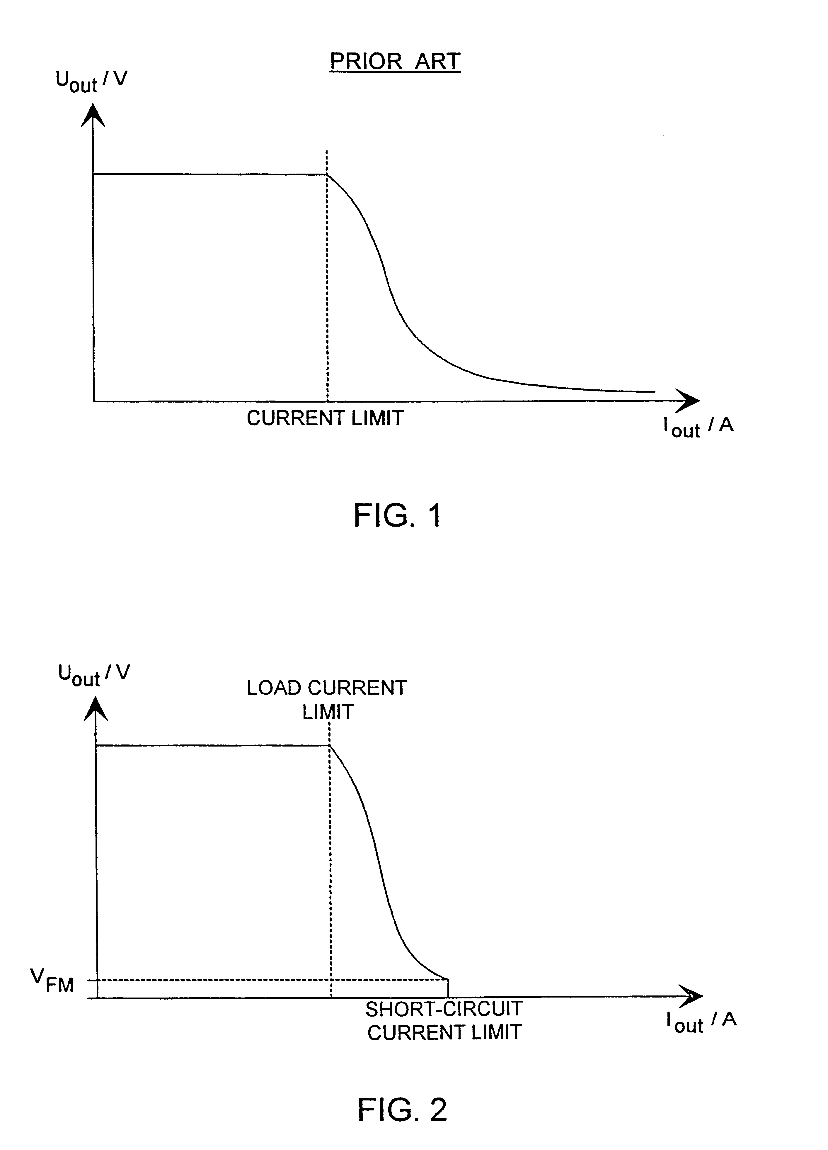
FIG. 1 shows a characteristic curve of a current-restricting arrangement according to the prior art. The current limit on the horizontal axis is here also the power limit at which limiting starts as the current continues to increase.

FIG. 2 shows a characteristic curve of a current-restricting arrangement according to the invention. On the horizontal axis we can see both the current limit and the maximum short-circuit current according to the invention to which the current is restricted in a short-circuit situation. V.sub.FM is the forward voltage drop of the diode connected in parallel with the switching transistor.

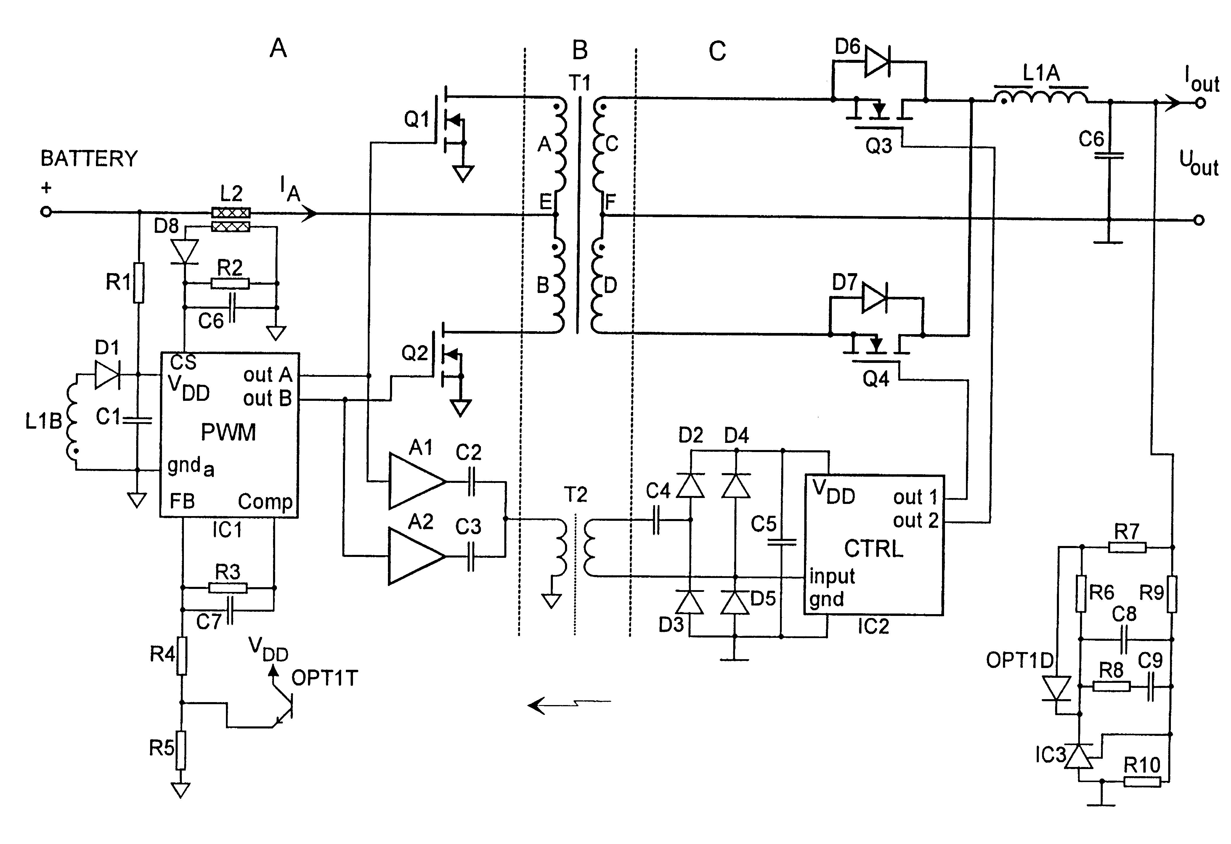
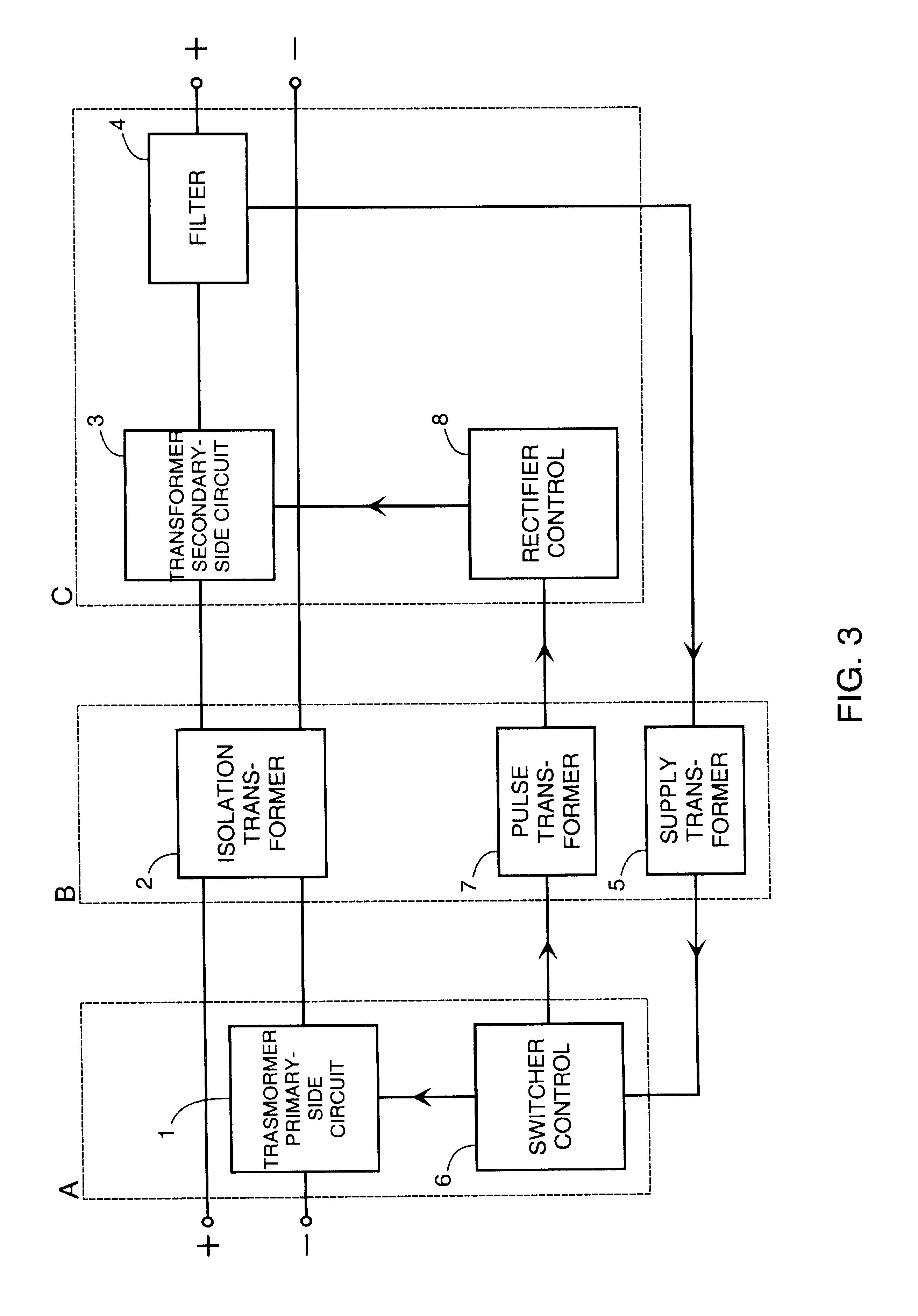
FIG. 3 shows a block diagram of a DC--DC power source applying the idea of the invention. Depicted in the figure is a transformer primary circuit 1, isolation transformer 2, transformer secondary circuit 3, filter 4 for rectified current and, further, a supply transformer 5 for rectification control, switcher control unit 6, pulse transformer 7, and a rectifier control un...


PUM


Abstract

A power source with an arrangement for restricting short-circuit current includes at least a primary-side switch block, a transformer unit and a rectifier. The rectifier includes switching transistors for rectifying the secondary side of the transformer. Operation of the rectifier depends on a control from a pulse-forming part of the primary-side switch block. Control for the switching transistors in the rectifier is interrupted when the output current of the rectifier exceeds a limit value. At least one other switch element is arranged parallel to each of the switching transistors in the rectifier to realize a secondary-side rectification in an overload situation.

Description

The invention relates to a power source comprising an arrangement for restricting a short-circuit current. A power source according to the invention includes a primary-side switch block, transformer unit and a rectifier which comprises at least one switching transistor. The invention further relates to a method for restricting the short-circuit current in a power source comprising a primary-side switch block, transformer unit and a rectifier which comprises at least one switching transistor.DESCRIPTION OF THE PRIOR ARTThere are known power sources which include an arrangement for restricting a short-circuit current. In one arrangement, current is switched off by a transistor on the basis of a rise in the voltage across a sensing resistor.From the prior art we further know of galvanically isolated power sources producing a d.c. voltage from a battery. Such power sources are utilized at least in connection with fixed telecommunication network equipment. A simple Buck switcher as well ...

Claims


Application Information

Patent Timeline
Patent Type & Authority Patents(United States)
IPC IPC(8): H02M3/24H02M1/00H02M3/335H02M1/32
CPCH02M1/32H02M3/33592Y02B70/1475Y02B70/10
Inventor PELKONEN, SEPPO
Owner NOKIA SOLUTIONS & NETWORKS OY
Why Eureka
Try Eureka