
Universal verification and validation system and method of computer-aided software quality assurance and testing

Inactive Publication Date: 2003-12-30
SOFEA INC
View PDF8 Cites 75 Cited by
  • Summary
  • Abstract
  • Description
  • Claims
  • Application Information

AI Technical Summary

Benefits of technology

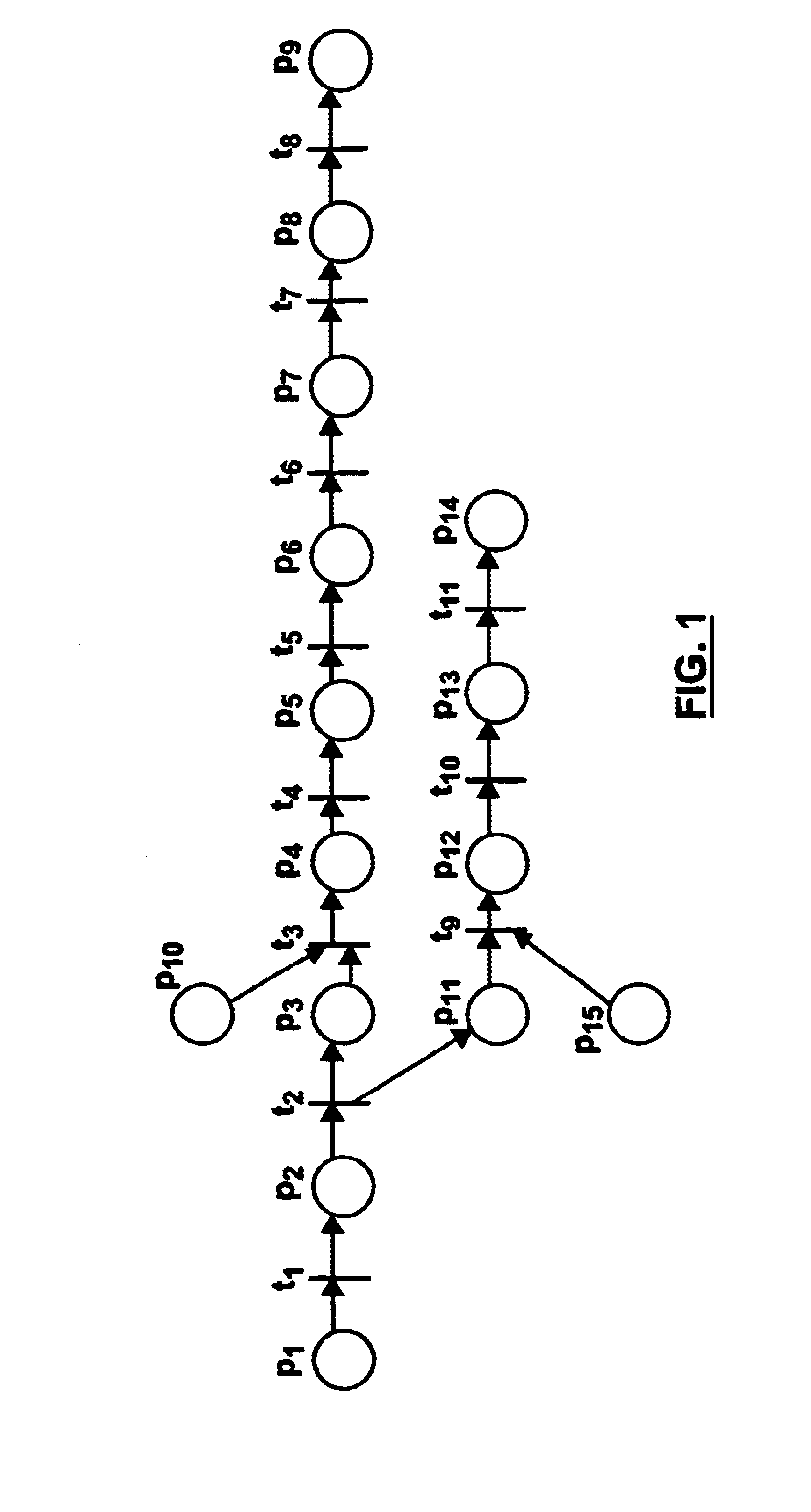
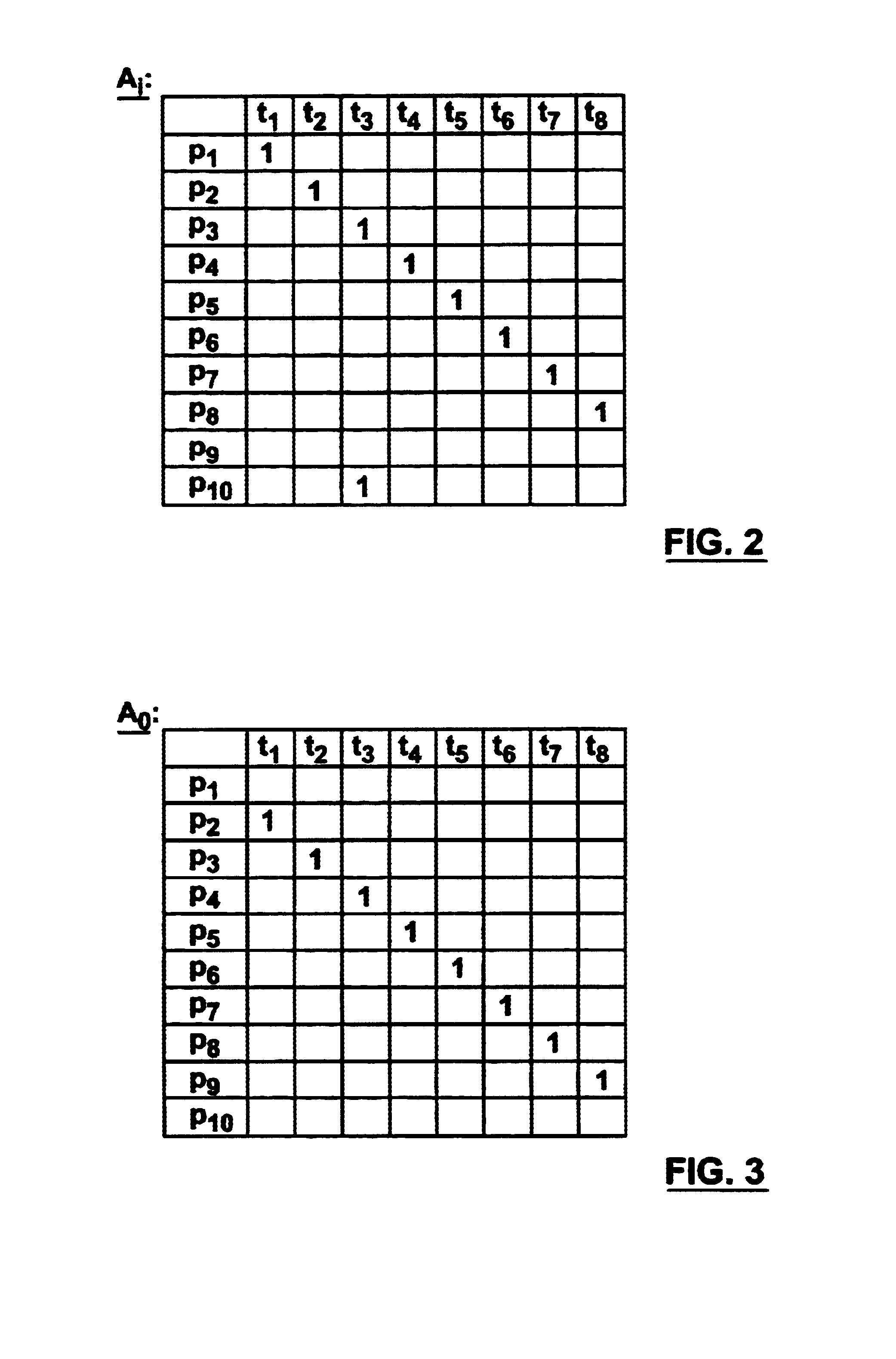
The invention accomplishes this by implementing a validation and verification process in each phase of the SDLC which represents the system requirements as a series of positions and transitions associated with natural language descriptions of the system requirements. In the preferred embodiment this involves creating a formal model of each phase of the SDLC to eliminate intra-phase inconsistencies and ambiguities and ensure completeness and compatibility, before proceeding to the next phase of the SDLC. These models are preferably based on classical Petri nets and variations or extensions thereof. In the preferred embodiment the models created in each phase are cross-reconciled, to eliminate inter-phase degradation by errors which may have been injected in the transition between SDLC phases.

Problems solved by technology

However, it has led to a `create, develop and test` software development approach, which is unsuitable and inefficient in the context of today's complex computer systems and networks.
This approach to software development presents problems at all three levels.
First, errors are introduced at each phase.
Because there is no universally accepted formal language available to describe the system requirements, the system developer's understanding of the user's requirements is subject to the vagaries and ambiguities of the informal language (for example, English) in which the requirements are conveyed.
There is no common frame of reference from which it can be determined whether the system requirements are consistent with the user's intent, and invariably due to the diversity of human experience and understanding, in many respects developer's understanding will not be consistent with the user's intent.
Thus, errors are introduced into the first phase of software development by inaccurate translation of the user's requirements into system requirements, and these errors are perpetuated throughout the remainder of the SDLC.
Errors are similarly introduced into the design phase, based on the extrapolation of the system requirements into design requirements, again due to the informality of the language used to represent these requirements at both levels.
These errors are cumulative with the errors introduced in the system requirements phase, and all of these errors become latent limitations of the system design phase.
At this stage none of these errors are manifest, because the end user typically does not participate in the SDLC after the first phase, and the end user has thus not received any feedback which would indicate that the user's requirements have been misunderstood and / or improperly translated into the design level.
Errors are introduced into the implementation phase in the same fashion, so that by the time the creation of the actual program code commences the initial system requirements as contemplated by the user are contaminated by three levels of errors.
In a complex computer system, immense time and effort is required to expose and correct these errors, and there is the possibility (in fact, a high probability) that errors will be overlooked and the software will be released for use with errors still in it.
This is at best an annoyance to the end user, and at worst can be catastrophic; for example in the case of computer systems for diagnostic or therapeutic use in hospitals, systems controlling functions in nuclear facilities, air traffic control systems etc.
Moreover, computer programs are incapable of resolving inherent inconsistency, incompleteness, incompatibility and ambiguity.
These deficiencies can arise at each stage of the SDLC, but the system requirements stage is acutely susceptible to the injection of such errors.
The end user may have a detailed understanding of their own requirements, but can rarely anticipate all possible results of any particular data entry or processing scenario, which leads to incompleteness and ambiguity errors; in the design requirements phase it is usually impossible to appreciate all possible ways and environments in which the system will be used, which leads to incompleteness and incompatibility errors; and in complex systems system behavior may be reliant upon thousands or even millions of processing steps, with many possible results, which can lead to ambiguity and inconsistency errors.
Complex computer programs are chaotic systems, in which a small error occurring early in a computational process can result in unpredictable and unproductive, or even counterproductive, system behavior.
This serves only to increase the complexity of the system, and is almost entirely a consequence of the `create, develop and test` approach to software development.
The cost and difficulty of rectifying an error in the implementation phase of the SDLC is orders of magnitude greater than the cost and difficulty of rectifying an error in the requirements phase or the design phase of the SDLC.
The testing of such systems is also problematic.
Being derivatives of the original program, however, the test programs will necessarily contain the same errors as the original program.
Thus, the results of further analysis using these derivative test programs may be satisfactory, or even excellent, but only because the test programs themselves are flawed in the same manner as the original program and therefore latent errors injected into the various stages of the SDLC cannot be detected by the tests.
There is no effective way to test the tests, because there is no standard methodology used to create the tests and therefore no way of validating the usefulness of the results.
There has heretofore been no widely used verification or validation model which can be applied universally to software created by different developers.
These problems are exacerbated by the explosive popularity of the Internet, which endeavors to accommodate software of many different types and platforms.

Method used


Image

  • Universal verification and validation system and method of computer-aided software quality assurance and testing
  • Universal verification and validation system and method of computer-aided software quality assurance and testing
  • Universal verification and validation system and method of computer-aided software quality assurance and testing

Examples


Embodiment Construction

The invention provides a method of modeling system requirements, design requirements and program code for a computer program, and a computer-aided software testing and quality assurance method and software using a universal verification and validation model which can be applied to any type of software modeled according to the invention.

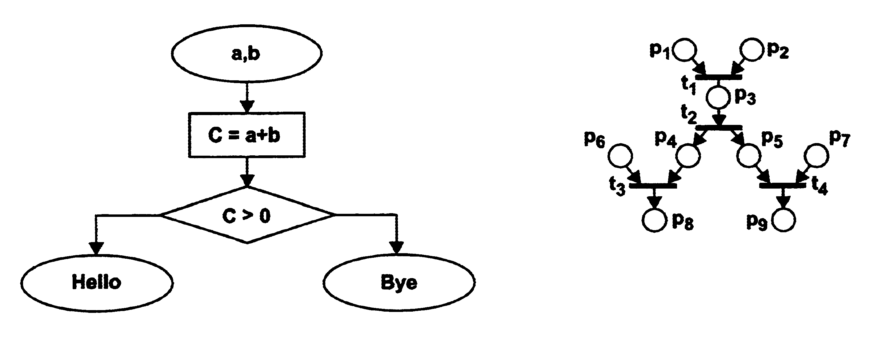
The invention utilizes a variation of Petri net modeling. As is known to those skilled in the art, a Petri net expresses conditions and events as a graph of connected positions and transitions. Petri net positions are marked by an indicator (for example a token) as corresponding conditions satisfied. Depending upon the variation of the Petri net, when one or more input positions are marked the output transition occurs, the indicator is removed from the input position(s) and an indicator is applied to the output position(s). The output position(s) may also be input positions for one or more subsequent transitions, which occur in like fashion. The Petri...


PUM


Abstract

A method of developing a model of a computer program represents the system requirement conditions and events as a set of positions and transitions, maps the system requirements in a table of positions with position and optionally transition designations, tags one or more significant positions in the including any conditional positions, and creates a reference designation associating alternative conditions with their respective conditional positions. A universal software test development method can be applied to the model by mapping the conditions to a set of positions including a starting position which has no input, a terminal position which has no output, and intermediate positions between the starting position and the terminal position, and generating from the set of positions a table of positions, associating each positions with an expression of the position representing the corresponding system requirements. Both the model development method and the test development method can be implemented automatically by computer software, and the test development method allows for automated development of test documentation. These methods can thus be applied for the verification and validation of computer software.

Description

FIELD OF INVENTIONThis invention relates to computer programs. In particular, this invention relates to a method of developing and testing computer programs, and computer software for implementing the method.BACKGROUND OF THE INVENTIONThe use of computers for home, commercial, industrial and academic applications has expanded exponentially in the past two decades, to the point where computers are now amongst the most versatile tools known to mankind. In large part this is due to software development, which can be credited for the versatility and complexity of today's myriad computer functions.The software development life cycle (SDLC) has conventionally consisted of three phases: 1. Determining system requirements through information from the intended user, which typically involves a detailed interrogation of the user to determine the user's objectives, and extrapolation from the developer's understanding of these objectives to determine the desired system behavior under the circums...

Claims


Application Information

Patent Timeline
IPC IPC(8): G06F9/44G06F11/36
CPCG06F8/73G06F11/3696G06F11/3608
Inventor PASSOVA, SOFIA
Owner SOFEA INC
Learn More