Combustion turbine power generation system and method of controlling the same

a technology of combustion turbines and power generation systems, which is applied in the direction of electric generator control, dynamo-electric converter control, dynamo-electric gear control, etc., can solve the problems of high turbine efficiency and inability to always operate turbines

Inactive Publication Date: 2004-02-03
HITACHI LTD
View PDF6 Cites 18 Cited by
  • Summary
  • Abstract
  • Description
  • Claims
  • Application Information

AI Technical Summary

Problems solved by technology

However, since the efficiency of turbine is influenced by a temperature of suction air or the like, the turbine cannot be always operated at the number of revolutions that the highest efficiency and a low Nox (nitrogen oxide) are attained for a certain fuel quantity.
Accordingly, it is difficult that the efficiency of the turbine is always kept to be high.

Method used


Image

  • Combustion turbine power generation system and method of controlling the same
  • Combustion turbine power generation system and method of controlling the same
  • Combustion turbine power generation system and method of controlling the same

Examples


embodiment 2

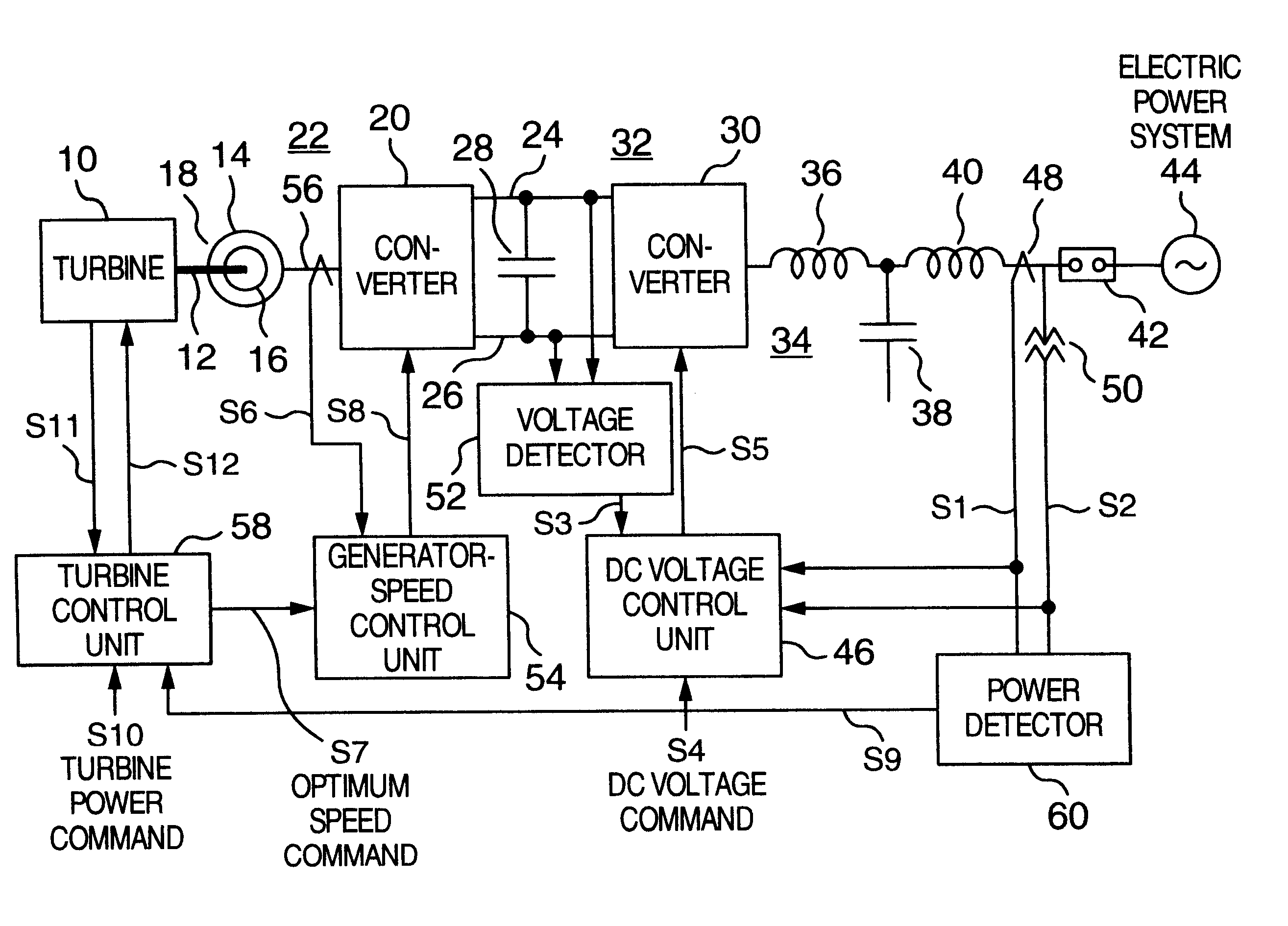
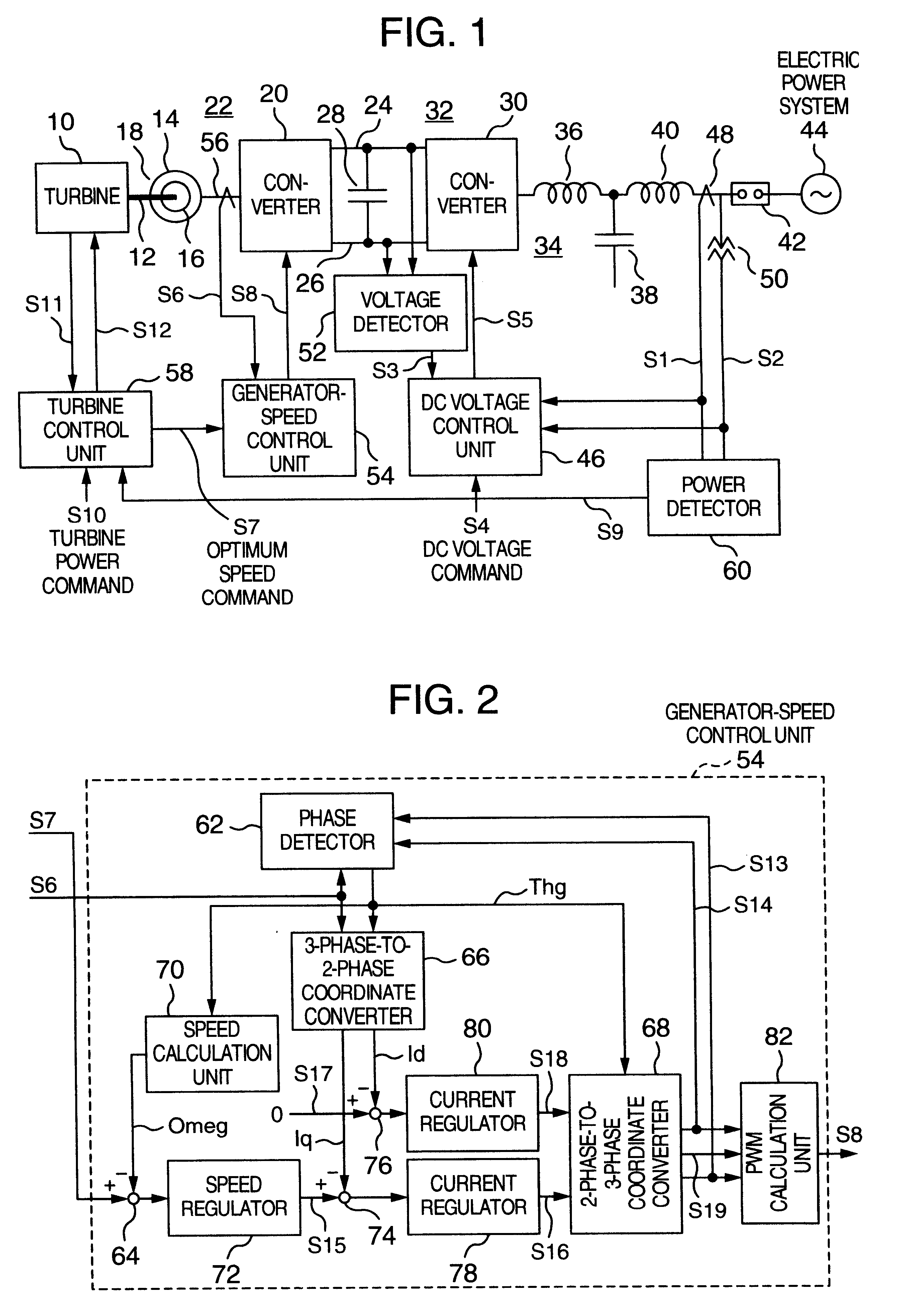
FIGS. 6 to 8 schematically illustrate another embodiment for realizing a combustion turbine power converting apparatus and a control method of the present invention. The generator-speed control unit 118 of FIG. 6 is different in partial configuration from the generator-speed control unit 54 of the embodiment 1.

The optimum speed command value S7 inputted from the turbine control unit 58 is supplied to a speed command calculation unit 116 and an output of the speed command calculation unit 116 is used as the speed command value. The generator-speed control unit 54 of FIG. 1 can be replaced by the generator-speed control unit 118. Other configuration shown in FIG. 6 is the same as FIG. 2 and accordingly detailed description thereof is omitted.

FIG. 7 is a block diagram schematically illustrating the speed command calculation unit 116 shown in FIG. 6. The speed command calculation unit 116 is supplied with the d-axis current detection value Id (exciting current component), the q-axis cur...


PUM


Abstract

A combustion turbine power generating system includes an AC power generator, a combustion turbine that drives the AC power generator, a first converter that can make conversion between AC current and DC current and having an AC side connected to the AC power generator, a second converter that can make conversion between AC current and DC current and having a DC side connected to a DC output side of the first converter, a smoothing condenser connected between the first and second converters, a generator-speed control unit that controls the first converter and a DC voltage control unit that controls a DC-side voltage of the second converter, thereby the generator-speed control unit controls the first converter on the basis of the number of revolution command value.

Description

1. Field of the InventionThe present invention relates to a combustion turbine power generating system that can realize high efficient and high reliable operation and method of controlling the same.2. Description of Related ArtAs disclosed in JP-A-09-289776, in a case of a conventional combustion turbine power generating system, a command value for number of revolutions is calculated from a load power to be outputted and the command value for the number of revolutions is inputted to a turbine controller to control the number of revolutions for a combustion turbine, thereby controlling the number of revolutions for a power generator.In the above technique, the command value for the number of revolutions is calculated from the output power of the turbine on the basis of the knowledge that the output power of the turbine is proportional to its the number of revolutions.The turbine controller adjusts a quantity of fuel to be fed on the basis of the command value for the number of revolu...

Claims


Application Information

Patent Timeline
Patent Type & Authority Patents(United States)
IPC IPC(8): F01D15/00F01D15/10F02C7/36F02C7/00H02P9/42H02P9/00H02P9/04F02C9/00H02P9/48H02P21/00H02P21/02H02P21/18H02P21/22H02P21/24H02P23/02H02P23/16H02P27/04H02P27/08
CPCF01D15/10F02C7/36H02P9/04H02P9/42
Inventor ICHINOSE, MASAYAFUTAMI, MOTOOARITA, HIROSHI
Owner HITACHI LTD
Why Eureka
Try Eureka