Relay device

a technology of relays and components, applied in the direction of relays, non-polarised relays, electromagnetic relay details, etc., can solve the problems of difficult mechanical adjustment of relays, difficult to reduce manufacturing costs, and inability to perform the final mechanical adjustment of gaps between fixed contact members and movable contact members,

Inactive Publication Date: 2004-02-03
ANDEN CORP
View PDF3 Cites 9 Cited by
  • Summary
  • Abstract
  • Description
  • Claims
  • Application Information

AI Technical Summary

Benefits of technology

With the relay device in accordance with the present invention, the stems of the electromagnetic relays are made integral with each other. And accordingly, the stems, each being integrally formed with each wiring member by resin molding method or the like, can be manufactured by one molding work. Accordingly, the resin molding process can be greatly shortened, and the number of parts therefor can be reduced. And where other parts of the electromagnetic relays are mounted on the common base plate with which the stems are integrally formed, the packaged position thereof can be determined in designed positions on the common base plate with only one positioning work. Accordingly, the packaging work becomes easy. In addition, the connection of the external connection terminals provided on the common base plate with an external wiring can be performed by one connection work, and accordingly, the wiring work can be performed with ease. Furthermore, by merely securing this common base plate, the mounting work of each electromagnetic relay is completed, and accordingly, the electromagnetic relays can be mounted with ease.
In preferred embodiments, the electromagnetic relay units are arranged in a line on the packaged surface of the common base plate. With this arrangement, the direction of the mechanical adjustment of the electromagnetic relay units can be made identical to each other, and accordingly, the mechanical adjusting operation can be made simple, and the above-described working space is not required to provide between electromagnetic relay units. Therefore, the device can be made small and light, and the length of a common wiring part between electromagnetic relay units can be made short.

Problems solved by technology

However, in the above-described conventional relay device, there are many parts and many electrical connections between these parts, and the manufacturing process is complex so that it is difficult to reduce the manufacturing costs greatly.
This relay device has adopted the arrangement that movable members of a relay unit move in the direction at right angles to a flat main surface of the common base plate, on which the relay unit is packaged, and accordingly, has the problem that the mechanical adjustment of the relay is very difficult after assembling thereof.
Namely, in this relay device, the fixed contact member is composed of the wiring member on the common base plate, and accordingly, upon manufacturing the relay unit, it is impossible to perform the final mechanical adjustment of a gap between the fixed contact member and a movable contact member, or the like.
In this case, other members may obstruct the insertion of the gauge to make the insertion work difficult.
In addition, these obstructive members must be arranged in the positions spaced from the above-described gap, and accordingly, the overall device becomes undesirably great.
These problems become remarkable where a plurality of relays are arranged on the common base plate.
With this arrangement, it is difficult to reduce the manufacturing costs further by making the manufacturing process simple.

Method used


Image

  • Relay device
  • Relay device
  • Relay device

Examples


first embodiment

a relay device in accordance with the present invention will be explained with reference to accompanying drawings.

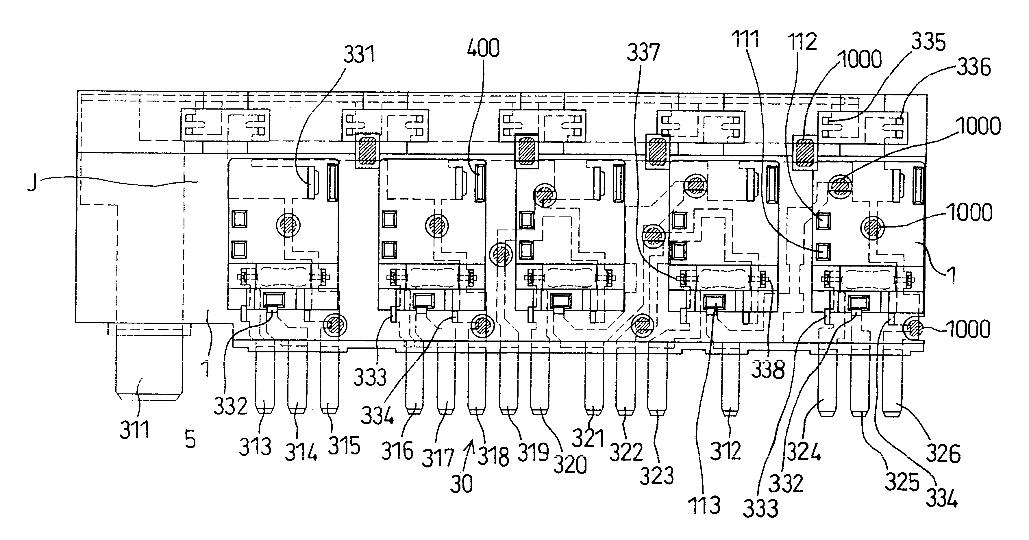
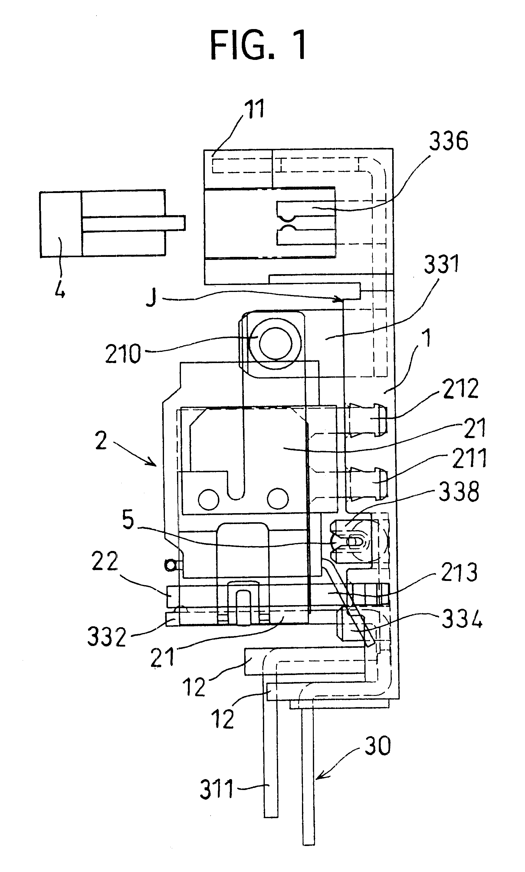
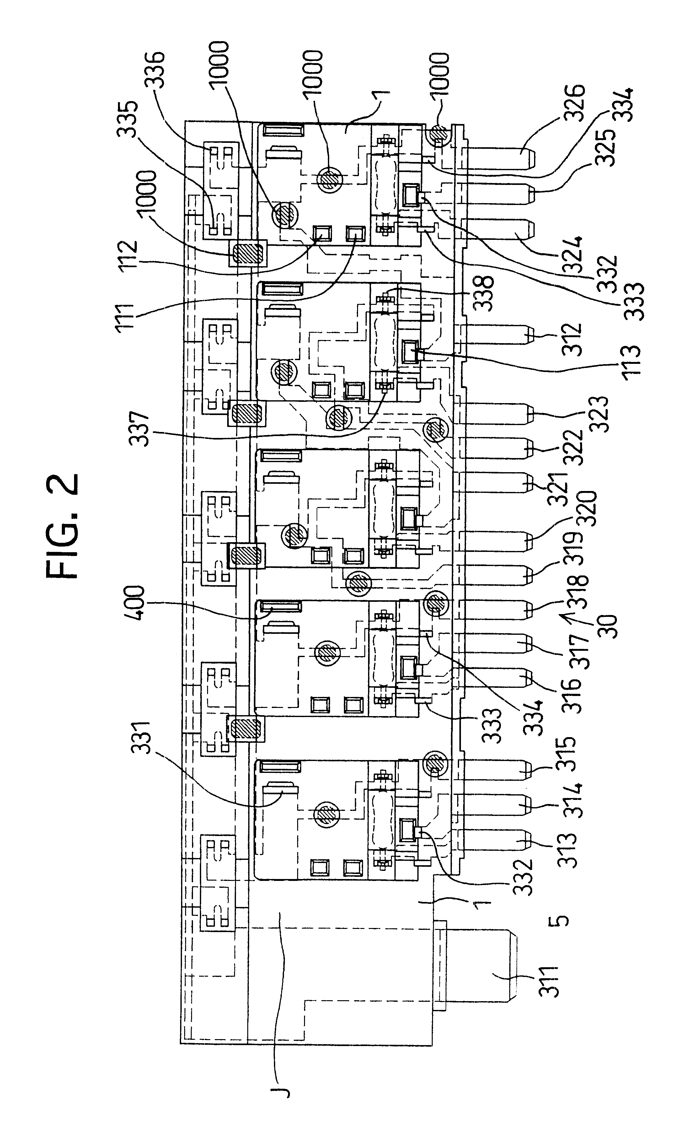
The side elevation view of this relay device is shown in FIG. 1, the front view of a common base plate 1 and wiring members 3 is shown in FIG. 2, the front view of a relay unit 2 is shown in FIG. 3, and the front view of half-finished wiring members 3 is shown in FIG. 4.

As shown in FIG. 1, the common base plate 1 as a wiring board, which is composed of resin, has a generally rectangular and flat configuration, and includes a frontwardly opening window 11 for accommodating a fuse in an upper portion thereof, and a wall 12 which projects frontwardly from a surface J of the base plate 1 on which parts are to be packaged, in a lower end thereof.

Five sets of relay circuits, each being composed of one relay unit 2, one fuse 4 and one resistor 5, are arranged on the surface J of the common base plate 1.

Wiring members 3 (FIG. 4), each extending into a predetermined configuration...

second embodiment

a relay device in accordance with the present invention will be explained with reference to FIGS. 5 to 8. The reference numerals and characters which are used in these drawings for explaining the present embodiment are not related to those which were used in FIGS. 1 to 4 for explaining the first embodiment. FIG. 5 is a front view of a relay device of the present embodiment, and FIG. 6 is a bottom view thereof. In FIG. 5, only one relay is illustrated. Actually, a plurality of relays are packaged on a common base plate 17.

Construction

Reference numeral 10 designates a fixed contact, 11 designates a movable contact which faces the fixed contact 10 so as to be able to come into contact with and separate from the fixed contact 10. Reference numeral 12 designates a leaf spring to which the movable contact 11 is secured. The leaf spring 12 elastically biases the movable contact 11 in a direction away from the fixed contact 10, and defines a current-carrying route to the movable contact 11....

modified embodiment

In the preceding embodiment, the method of adjusting the contact gap L using the deformation of the stopper 19 has been explained. Of course, the contact gap L may be adjusted by deforming the holding member 18 which supports the fixed contact 10. The adjusting method using the deformation of the holding member 18 will be explained with reference to FIGS. 9 and 10. The holding member 18, the fixed contact 10, the movable contact 11 and the leaf spring 12 which are illustrated in FIG. 9 are arranged, similarly to the arrangement of FIG. 5.

The holding member 18 has a first plate member 18a which is partly embedded in the common base plate 17 (not shown), projects from the common base plate 17, and extends in parallel with the surface 17a toward the movable contact 11, and a second plate part 18b which extends from an end of the first plate part 18a in the direction away from the surface 17a, and the fixed contact 10 is secured to the second plate part 18b and faces the movable contact...


PUM


Abstract

A relay device capable of reducing the manufacturing costs thereof by decreasing the number of parts and the number of electrical connections between these parts, and making the manufacturing process simple. The relay device has a plurality of electromagnetic relays and uses a common base plate with which stems of the electromagnetic relays are formed integrally, and on which a wiring member is formed by resin molding. The wiring member on the common base plate is projected from the molded resin to define a fixed contact member of each electromagnetic relay. Each relay unit assembly of each electromagnetic relay except for the fixed contact member thereof is secured to the common base plate such that a movable iron piece is driven in parallel with a surface of the common base plate. The construction of the resultant relay device is compact, the relay properties are readily adjusted, and the number of parts can be reduced.

Description

1. Field of the InventionThe present invention relates to a relay device.2. Description of Related ArtA conventional relay circuit includes a plurality of relays which are electrically connected to each other, and is generally manufactured by preparing a wiring board on which a predetermined wiring is provided and to which a plurality of sockets for relays are secured, and fitting relays into respective sockets secured to the wiring board. Otherwise, such a conventional relay circuit may be manufactured by directly securing external connection terminals (contact terminals, coil terminals) to the wiring provided on the wiring board by soldering or the like method without using sockets.As is well known, the conventional relay includes contact members composed of a movable contact member and a fixed contact member, a magnetic path member which generates magnetic force for driving the movable contact member, a coil which forms magnetic flux for driving the movable contact member in the ...

Claims


Application Information

Patent Timeline
Patent Type & Authority Patents(United States)
IPC IPC(8): H01H50/04H01H50/02H01H11/00H01H9/10H01H50/14H01H9/00H01H50/00H01H50/44H01H49/00H01H45/00H01H9/02H01H51/20
CPCH01H50/043H01H50/047H01H9/10H01H11/0056H01H49/00H01H50/14H01H50/443H01H2050/049
Inventor SUZUKI, HIROHISA
Owner ANDEN CORP
Why Eureka
Try Eureka