Method and system for controlling operation of an energy conversion device

a technology of energy conversion device and solar collector, which is applied in the direction of machines/engines, transportation and packaging, light and heating equipment, etc., can solve the problems of inability to accurately damage to solar collector systems, and difficulty or inability to correctly issue new commands or instructions

Inactive Publication Date: 2004-02-10
LEIDOS
View PDF9 Cites 65 Cited by
  • Summary
  • Abstract
  • Description
  • Claims
  • Application Information

AI Technical Summary

Problems solved by technology

One complication arising from the use of solar collectors or concentrators is that high wind conditions may cause damage to solar collector systems because solar collectors are typically placed on a pedestal above the ground.
If an error in the system occurs, it is difficult or impossible to issue new commands correctly.
That is, if the program implementing the algorithm is unable to determine the correct orientation of the solar collector from its past history, it cannot accurately issue new commands or instructions.
Error detection is also difficult in such a system.
If the program implementing the algorithm has an error, it will continue to operate even though it may be issuing commands based on incorrect assumptions about the solar collector orientation.
If such a system is turned off and restarted in mid-operation, the program routine does not have correct starting parameters, and therefore, is unable to issue correct control commands.
The use of such membranes, however, may give rise to complications in operation.
If the engine cannot accept the power available from the concentrator at any given time, due to optional focusing at high solar radiation levels, it will overheat.
One solution has been to off-track, i.e., no longer track the sun, with the dish, but this drops system output to zero, and may overheat other components that the beam tracks across.
This is costly, and leads to lower system efficiency since the engine operates lower on its power curve most of the time.
Such overheating can also occur in the case where a concentrator includes fixed focus mirrors and the power input to an energy conversion device exceeds a predetermined amount.
It leads to shutdown of solar and fuel operation, and stowing of the dish until the fault is reset from the SCADA system.
In general, fault and override conditions lead to the system shutting down and stowing.
Face-down stow introduces some complications to the algorithms.

Method used


Image

  • Method and system for controlling operation of an energy conversion device
  • Method and system for controlling operation of an energy conversion device
  • Method and system for controlling operation of an energy conversion device

Examples


Embodiment Construction

The following example of an embodiment of the invention is provided for illustration.

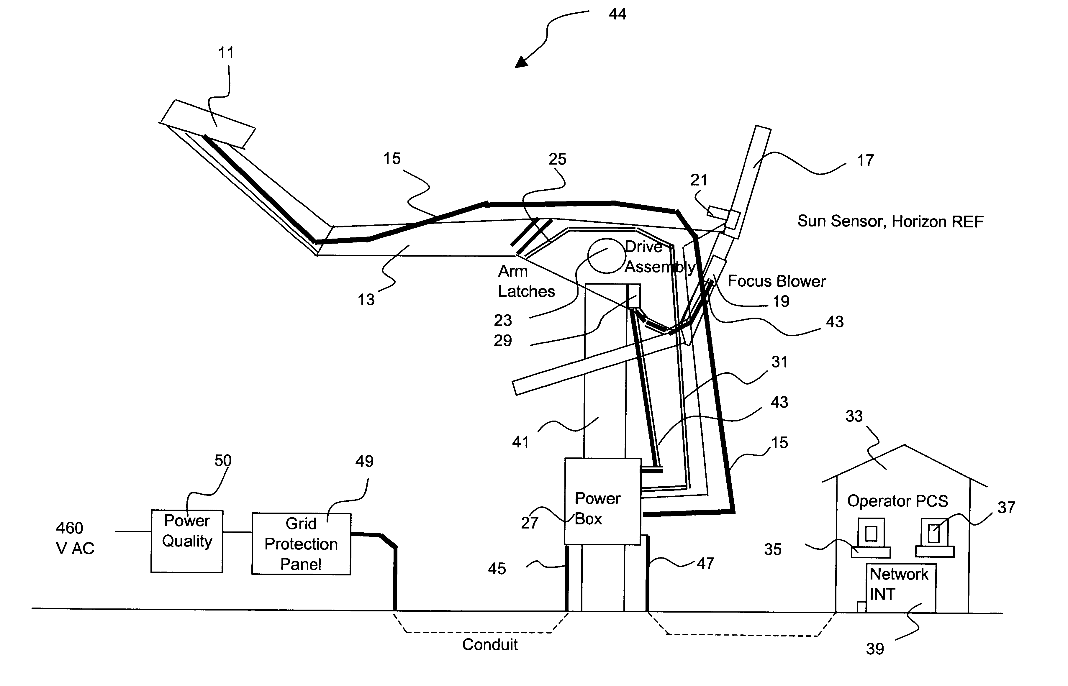
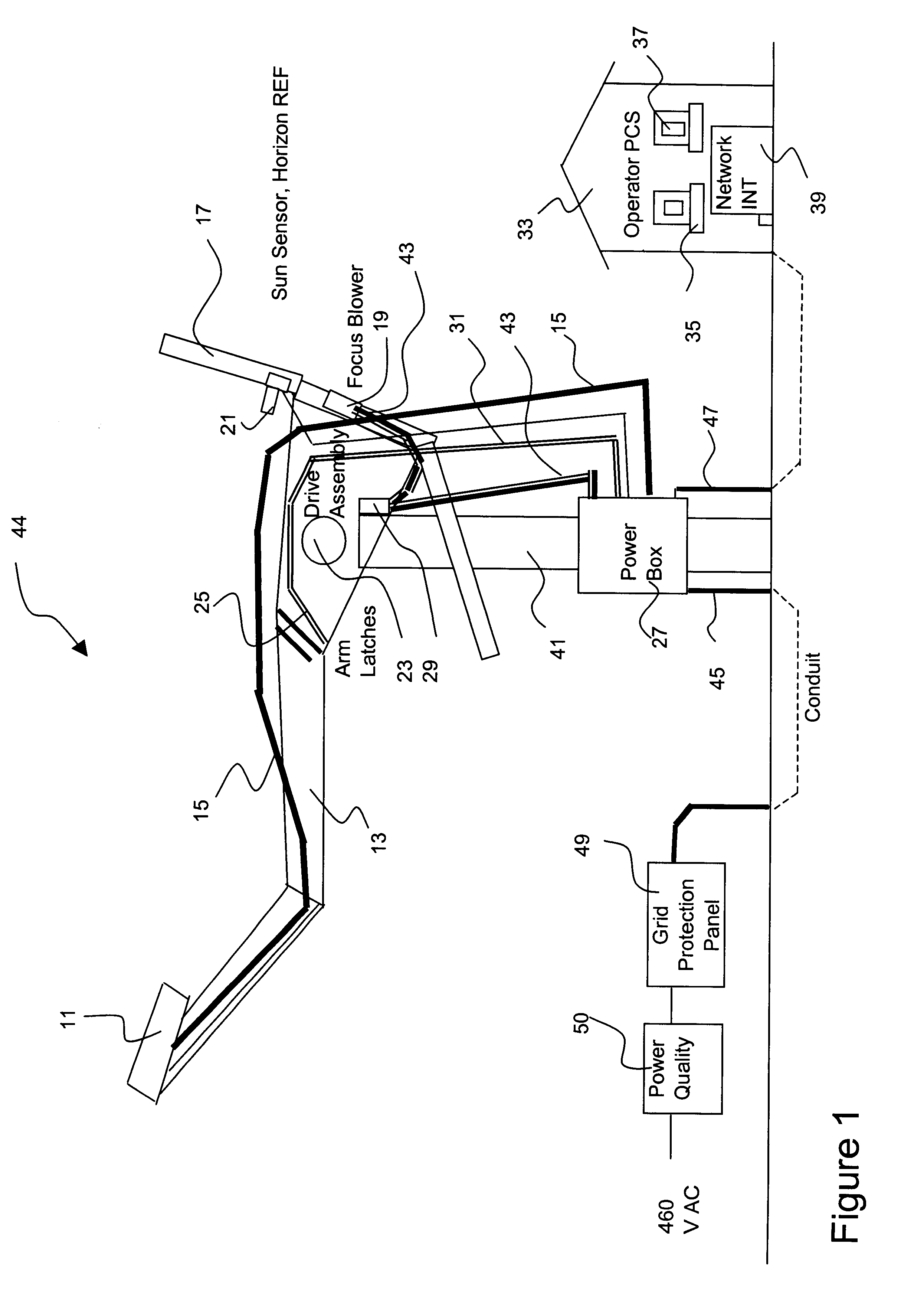
Referring again to FIG. 1, multiple solar collector systems 44 may be connected to a serial network over which commands are received from the operator terminal 35 and status information is transmitted to the operator terminal 35 from multiple solar collector systems 44. Serial data transmission is provided.

Stirling Engine Communications

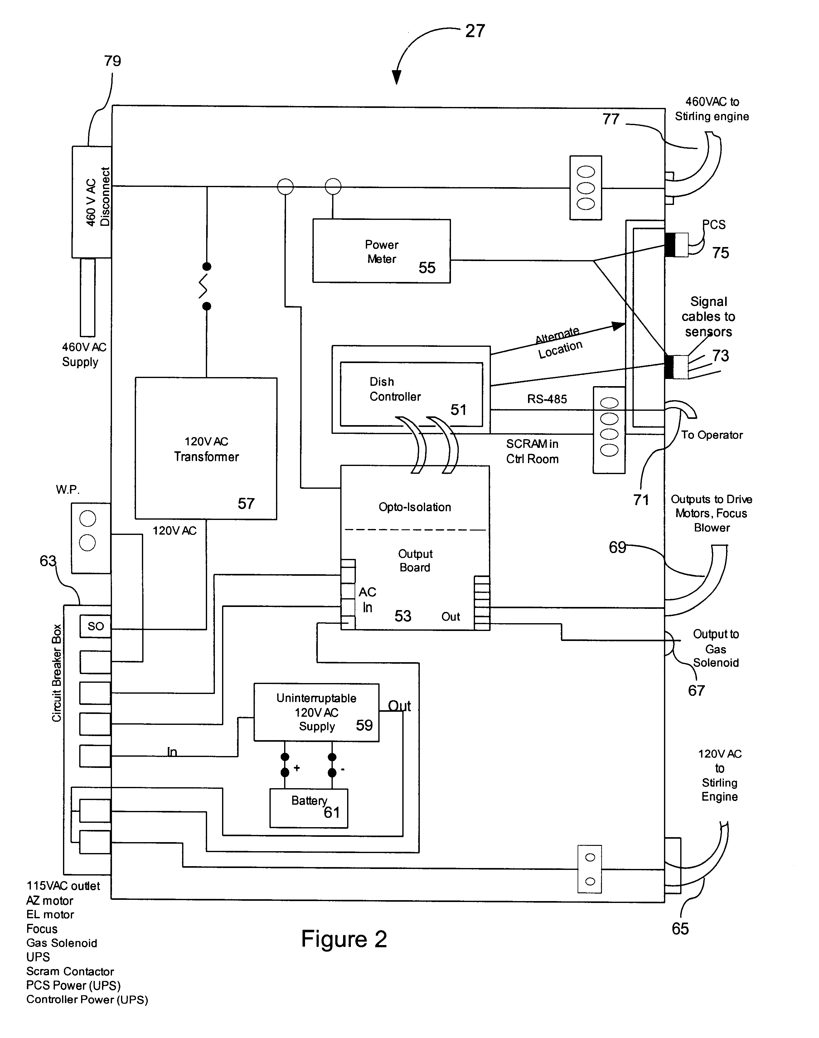
A dedicated serial connection connects the dish controller and the Stirling engine controller. A serial connection comes from the Stirling engine controller and is connected to the computer network 39 at the user station 33. Electrical isolation between the Stirling engine controller and the dish system controller and the dish controller and the serial link to the Stirling computer network 39 is provided.

Electrical Power Input

The solar collector system 44 accepts and supplies alternating current ("AC") power as follows:

The grid protection panel 49 is equipped with rel...


PUM


Abstract

A method and system is described for controlling a solar collector. A microprocessor receives inputs from one or more sensors in the system and determines the level of operation of an energy conversion device. If the level of operation reaches a predetermined setpoint below a maximum level at which the device is to operate, a variable focus solar concentrator is defocused to reduce energy input into the energy conversion device. When the system cools down and operates at a second predetermined level, lower than the first predetermined level, the concentrator is then refocused to increase the power input to the energy conversion device.

Description

1. FIELD OF THE INVENTIONThe invention relates to a system and method for controlling a solar collector or solar concentrator. More specifically, the system and method relate to a controller system and associated software for accepting sensor inputs from sensors on the solar collector to determine the state of operation of an energy conversion device associated with the concentrator. In particular, the sensors provide information relative to the energy conversion device operating above a certain capacity, indicated, for example, by overheating, and the controller system issues commands to control the focusing of the solar collector, and executing instructions based on the energy conversion device condition to avoid operation above a desired capacity, while maintaining the energy conversion device online and operational.2. BACKGROUND OF THE INVENTIONSolar collector or concentrator systems are used to collect solar energy from sunlight and convert it to a usable form of energy. The te...

Claims


Application Information

Patent Timeline
Patent Type & Authority Patents(United States)
IPC IPC(8): F24J2/40
CPCF24J2/40Y02E10/46F24S50/00
Inventor DAVENPORT, ROGER L.SMITH, DAVID C.
Owner LEIDOS
Why Eureka
Try Eureka