Sensorless control system for synchronous motor

a synchronous motor and control system technology, applied in the direction of motor/generator/converter stopper, dynamo-electric gear control, dynamo-electric converter control, etc., can solve the problems of increased possibility of ringing, reduced reliability, and high-frequency oscillations

Inactive Publication Date: 2004-02-10
HITACHI JOHNSON CONTROLS AIR CONDITIONING INC
View PDF15 Cites 73 Cited by
  • Summary
  • Abstract
  • Description
  • Claims
  • Application Information

AI Technical Summary

Problems solved by technology

However, there is a problem that reliability may be decreased by using a sensor 44 and a cost problem also arises because an expensive current sensor may be required to realize highly accurate control.
Further, the method shown in FIG. 34 has a problem of high-frequency oscillations (ringing) of a current caused by switching operations.
The possibilities of ringing occurring increase as the length of the wiring cable for the motor becomes longer, which makes it difficult to detect necessary current values.
Furthermore, when a rotational frequency of the motor is low, the width of a PWM pulse becomes narrow, therefore, even though the wiring cable is shortened, the method is affected by noise and detection accuracy deteriorates.

Method used


Image

  • Sensorless control system for synchronous motor
  • Sensorless control system for synchronous motor
  • Sensorless control system for synchronous motor

Examples


embodiment 1

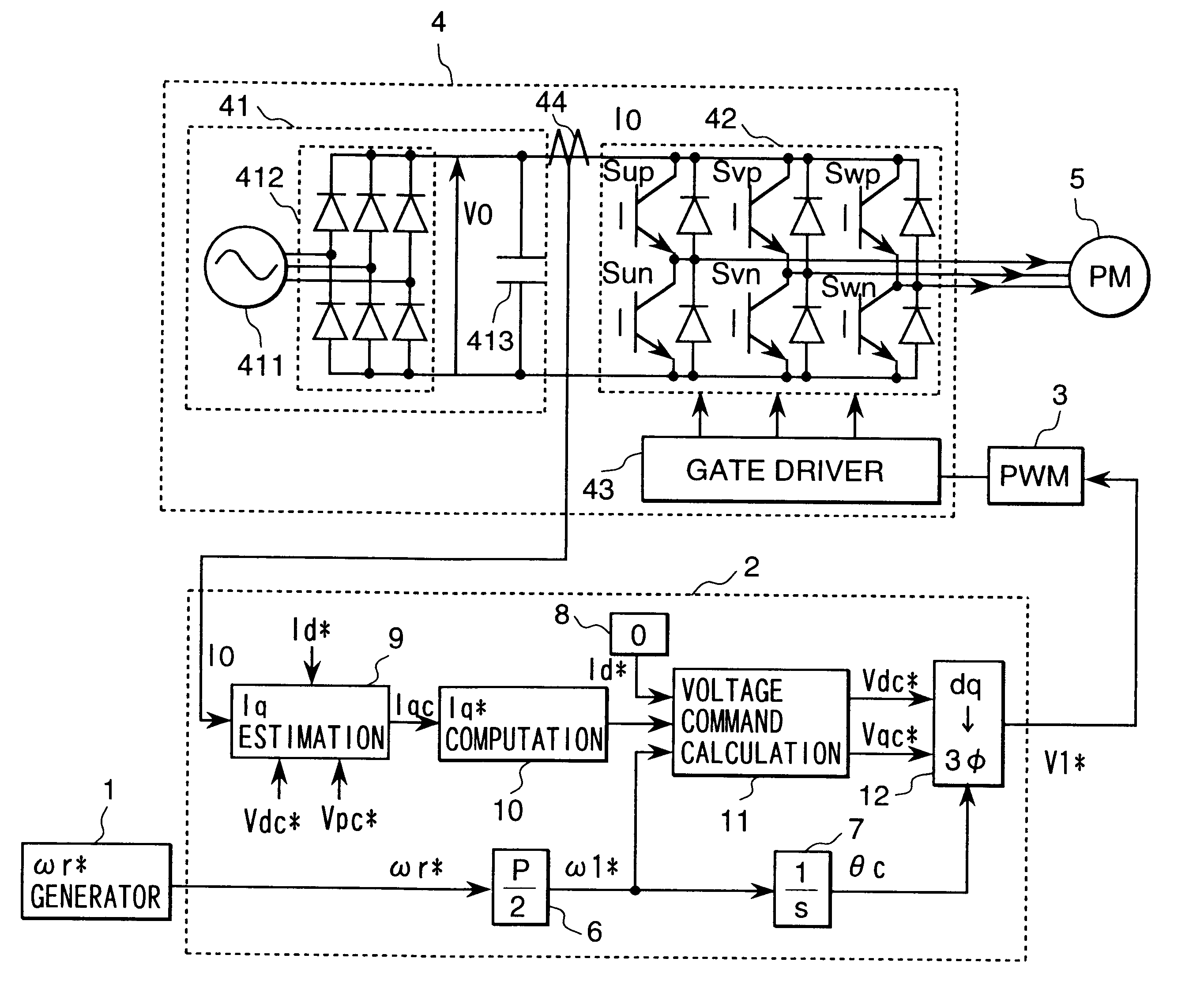
FIG. 1 is a configuration diagram of a first embodiment of the present invention. In FIG. 1, there are shown a speed command generator 1 which gives a rotational speed command .omega.r* to a motor, a controller 2 which computes the voltage applied to the motor, a PWM (pulse-width modulation) generator 3 which generates pulses to drive an inverter 4 based on a voltage command V1*, an inverter 4 which consists of semiconductor switching elements for driving the motor, a synchronous motor 5 which is a control target, a conversion gain 6 (P denotes the number of poles of the motor) which converts a rotational speed command .omega.r* to an electrical angle frequency command .omega.1* of the motor, an integrator 7 which computes an AC phase .theta.c in the controller based on the electrical angle frequency command .omega.1*, an Id* generator 8 which gives a current command Id* of the magnetic pole axis component (d-axis component) of the motor, an Iq estimator 9 which estimates and comput...

embodiment 2

A second embodiment of the present invention will be described in detail with reference to FIG. 5. FIG. 5 shows the configuration of a controller 2B which is used instead of the controller 2 shown in FIG. 1. Reference numerals 6 to 13 in FIG. 5 denote the same devices as represented in a first embodiment. An I0 damping gain 19 adds an adjustment value .DELTA..omega.I0 to an electrical angle frequency command .omega.1* using a detected DC current value I0 of an inverter. This embodiment adds the I0 damping gain 19 to a first embodiment.

Next, operations of a second embodiment will be explained. As shown in Equation (2), as a motor load changes and power consumption increases, a detected DC current value I0 increases if the DC voltage V0 is constant. Therefore, when the detected DC current value I0 increases, load disturbance occurs causing themotor speed to decrease. To cope with the load fluctuation without causing step-out of a motor, the speed of the controller may be reduced accor...

embodiment 3

A third embodiment of the present invention will be described with reference to FIG. 6. FIG. 6 shows the configuration of a controller 2C which is used instead of the controller 2 shown in a first embodiment. Reference numerals 6 to 13 in FIG. 6 denote the same devices as represented in a first embodiment. An Iq damping gain 20 adds an adjustment value .DELTA..omega.q to an electrical angle frequency command .omega.1* using the estimated torque current value Iqc. This embodiment adds the Iq damping gain 20 to a first embodiment.

Next, operations of a third embodiment will be described. A second embodiment uses a detected DC current value I0 to correct an electrical angle frequency command .omega.1*, while this embodiment uses an estimated torque current value Iqc to correct the electrical angle frequency command .omega.1*. The detected DC current value I0 is a physical quantity which fluctuates in response to power consumption of a motor, however, the value is not directly related to...


PUM


Abstract

A synchronous motor drive system in accordance with the present invention detects a DC current of an inverter which drives a synchronous motor, and based on the magnitude of the current, estimates torque current components that flow through the motor, and then based on the estimated value, determines the voltage which is applied to the motor, and finally estimates and computes the magnetic pole axis located inside the motor using the estimated value of the torque current.

Description

1. Field of the InventionThe present invention relates to a control system for a synchronous motor, and more particularly to a highly accurate and high-performance synchronous motor drive system whose controlling mechanism is made simple by not using sensors to detect the motor's speed and position or a motor current sensor.2. Descriptions of Prior ArtFIG. 33 shows a method for controlling a synchronous motor that does not detect the synchronous motor's magnetic pole position or motor current and does not use a position sensor either. This prior art uses a current sensor that detects a motor current instead of using a position sensor. This prior art is based on a synchronous motor vector control that uses a position sensor, but employs a magnetic pole position estimator and a speed estimator instead of a position sensor (hereinafter, this method is referred to as a "sensorless vector control method"). The configuration of this method, except for a magnetic pole position detecting se...

Claims


Application Information

Patent Timeline
Patent Type & Authority Patents(United States)
IPC IPC(8): H02P23/00H02P6/14H02P6/18H02P6/06H02P6/08H02P6/182H02P6/28H02P21/00H02P21/14H02P21/18H02P21/22H02P21/24H02P23/14H02P23/16H02P27/04H02P27/08
CPCH02P6/18H02P23/004H02P23/30
Inventor IWAJI, YOSHITAKAENDO, TSUNEHIROSAKAMOTO, KIYOSHITAKAKURA, YUHACHI
Owner HITACHI JOHNSON CONTROLS AIR CONDITIONING INC
Why Eureka
Try Eureka