Laser system with mixed polarity beamlets

a laser system and beamlet technology, applied in the field of laser systems, can solve the problems of poor uniformity, poor yield, poor uniformity of laser crystallisation process, etc., and achieve the effects of preventing inversion, reducing the loss of beam energy, and increasing the fluence jitter

Inactive Publication Date: 2004-02-10
INNOLUX CORP
View PDF3 Cites 18 Cited by
  • Summary
  • Abstract
  • Description
  • Claims
  • Application Information

AI Technical Summary

Benefits of technology

The present invention provides a laser system comprising a laser source for producing a laser beam having a first intensity profile in one transverse direction, and a lens system for modifying the first intensity profile, the lens system comprising a plurality of lens elements adapted to divide the beam into a plurality of beamlets across the first intensity profile, at least one of the beamlets outputted by the lens system being inverted relative to the others, such that a desired intensity profile is generated at the output of the laser system. This lens system enables the beam generated by the laser source to be modified so that the output of the laser system is altered as required for laser crystallisation, addressing the problem identified above. This is achieved substantially without loss of beam energy or increase in fluence jitter.
In a preferred embodiment, the lens elements are arranged in two spaced arrays, each extending along the one direction, the arrays being adapted to invert the at least one beamlet relative to the others. Alternatively, the lens system may comprise two spaced arrays of primary lens elements, each extending along the one direction, with pairs of lens elements, one from each array, being arranged to invert a respective beamlet, wherein one or more additional lens elements are included to prevent inversion of the at least one beamlet or to provide a further inversion of the at least one beamlet. Thus, for example, additional lens elements may be inserted in an existing lens system to adapt it in accordance with the invention. Prevention of inversion rather than further inversion is preferred, as the latter may lead to greater light losses and divergence of the beamlets leaving the lens system.

Problems solved by technology

However, the laser crystallisation process can give rise to poor yields, resulting from poor uniformity of the laser crystallisation process.
One factor contributing to this poor uniformity is the use of a simple so-called top-hat beam profile.
During cooling, a portion of the layer which has experienced full melt-through will recrystallise into a fine-grained structure giving rise to reduced quality in the final product.
Prevention of inversion rather than further inversion is preferred, as the latter may lead to greater light losses and divergence of the beamlets leaving the lens system.

Method used


Image

  • Laser system with mixed polarity beamlets
  • Laser system with mixed polarity beamlets
  • Laser system with mixed polarity beamlets

Examples


Embodiment Construction

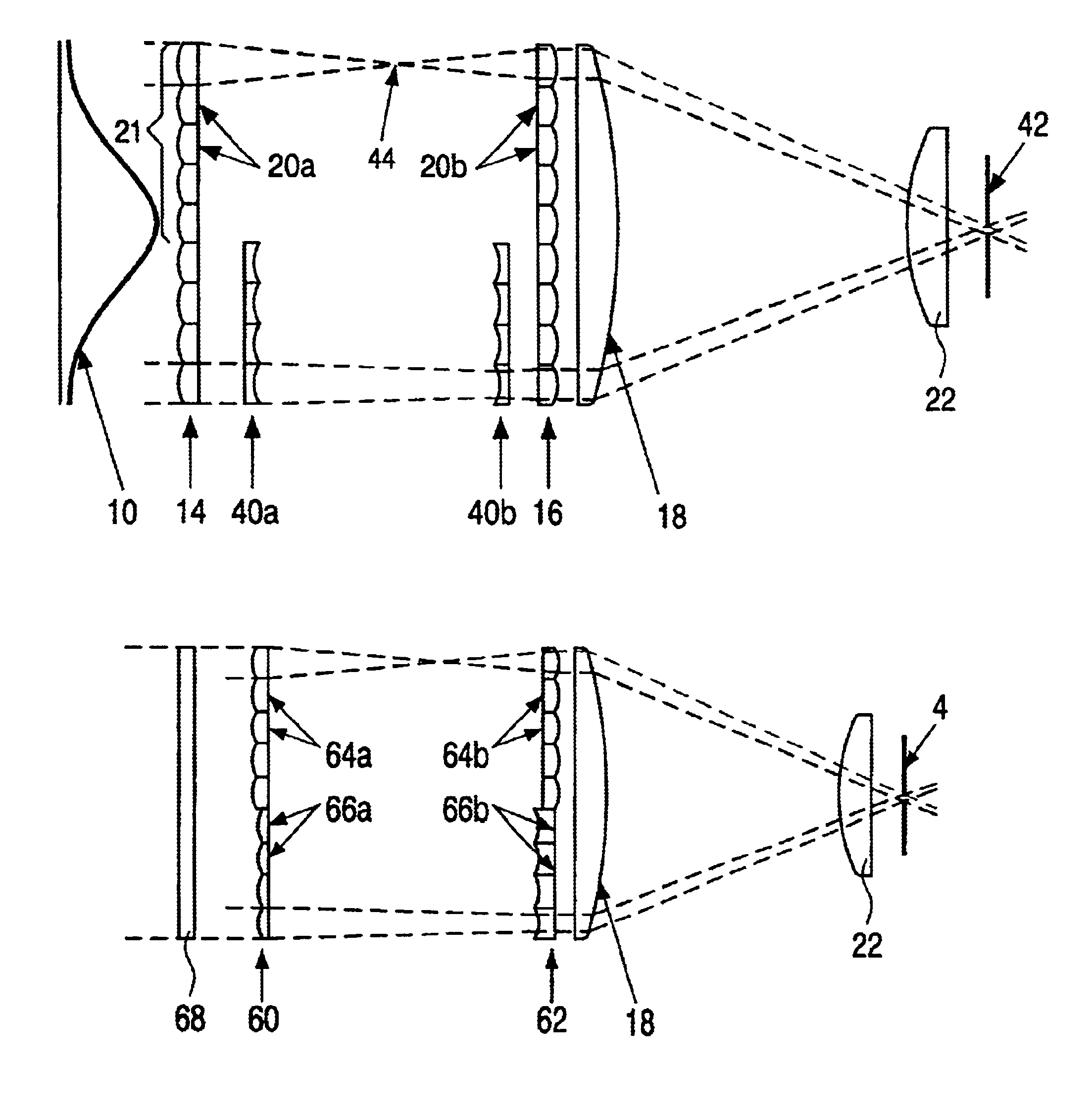
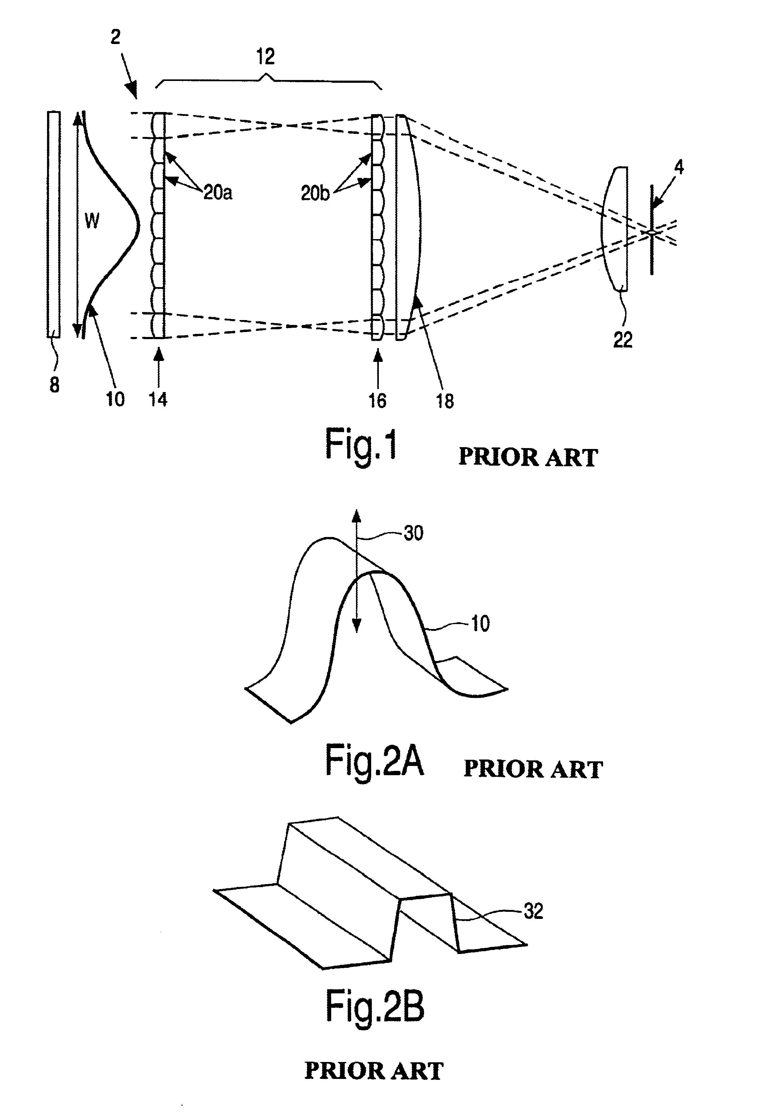
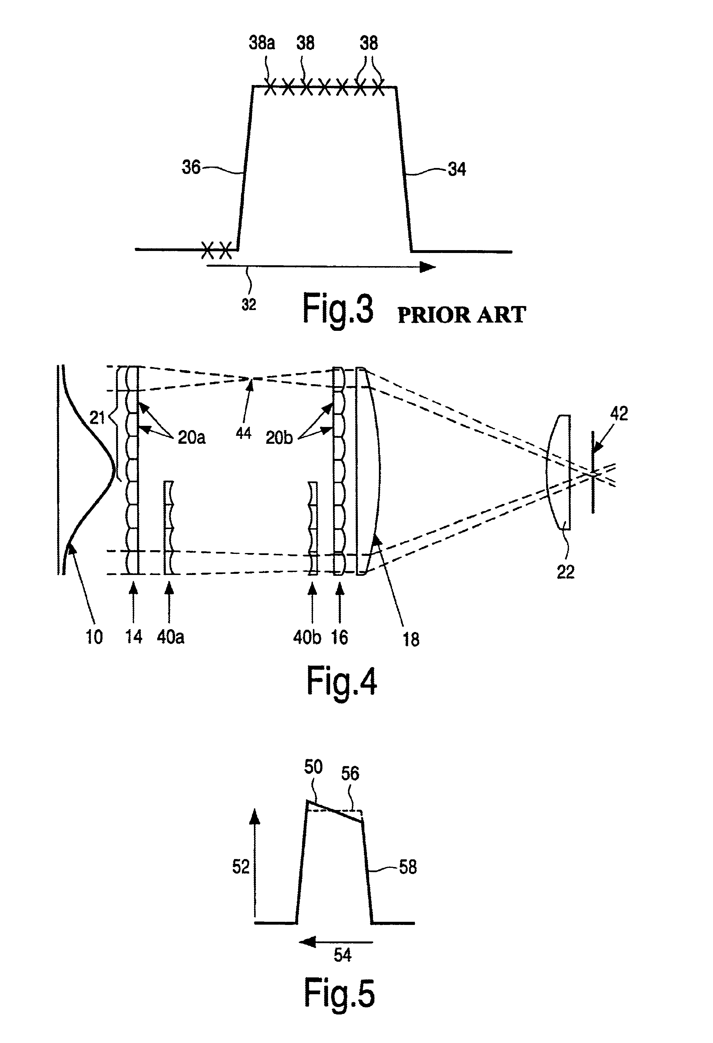
FIG. 1 shows selected elements of a known laser system 2 comprising a homogeniser 12. The homogeniser 12 is adapted to produce a laser output suitable for crystallisation of a semiconductor sample. The system 2 is for radiation of a sample (not shown) with a line beam 6 having a controlled intensity profile. Typically, the sample comprises a silicon film on an insulating substrate. The line beam 6 is scanned across the surface of the sample, and this is normally achieved by mounting the sample on a movable support (not shown).

The laser system comprises a laser source 8 which may generate a beam having a semi-Gaussian intensity profile. The output of the laser source is a light front or beam. In one dimension, transverse with respect to the direction of propagation of the beam, the intensity varies following a normal distribution, as represented by curve 10, whereas the intensity is constant following the transverse dimension orthogonal thereto. The width of the beam W may be approxi...


PUM

PropertyMeasurementUnit
widthaaaaaaaaaa
widthaaaaaaaaaa
widthaaaaaaaaaa

Abstract

In a laser system for laser crystallization of semiconductor films, a laser source produces a laser beam that is transmitted to a lens system having a plurality of lens elements adapted to divide the beam into a plurality of beamlets. At least one of the beamlets is inverted relative to the others, such that a desired intensity profile is generated at the output of the laser system.

Description

FIELD OF TECHNOLOGYThis invention relates to laser systems, particularly but not exclusively for providing output profiles suitable for laser crystallisation of semiconductor films, such as crystallisation of amorphous silicon to form polycrystalline silicon in thin film devices. The invention also relates to apparatus and methods for crystallising a semiconductor film using such a laser system.BACKGROUND AND SUMMARYIt is well known that the use of laser crystallisation processes can enable the manufacture of low-temperature poly-silicon devices, for example for displays or other circuits. However, the laser crystallisation process can give rise to poor yields, resulting from poor uniformity of the laser crystallisation process.One factor contributing to this poor uniformity is the use of a simple so-called top-hat beam profile. This form of output is typical of known laser beam homogenisers. The top-hat profile has a substantially constant intensity over the width of the profile. T...

Claims


Application Information

Patent Timeline
Patent Type & Authority Patents(United States)
IPC IPC(8): B23K26/073B23K26/06G02B27/09H01S3/00H01L21/20H01L21/268
CPCB23K26/073G02B27/09G02B27/0927G02B27/0961H01S3/005C30B30/00
Inventor MCCULLOCH, DAVID J.CLARKE, JOHN A.
Owner INNOLUX CORP
Why Eureka
Try Eureka