
Longitudinal adjustment device for vehicle seats

a technology of longitudinal adjustment and vehicle seat, which is applied in the direction of chairs, movable seats, machine supports, etc., can solve the problems of inability to adjust longitudinally, inability to compensate for manufacturing tolerances,

Inactive Publication Date: 2004-02-24
KEIPER GMBH & CO KG
View PDF27 Cites 14 Cited by
  • Summary
  • Abstract
  • Description
  • Claims
  • Application Information

AI Technical Summary

Benefits of technology

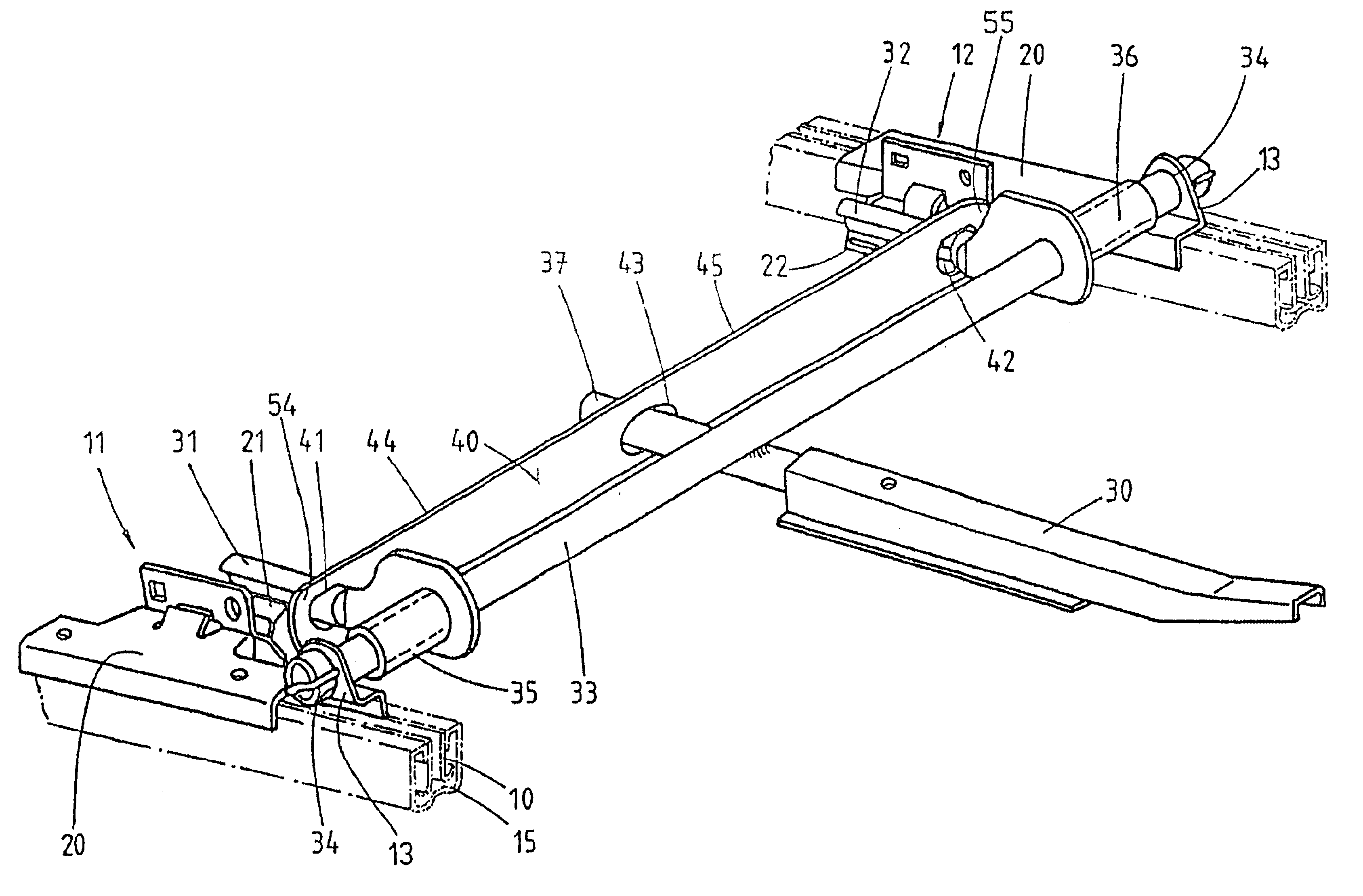
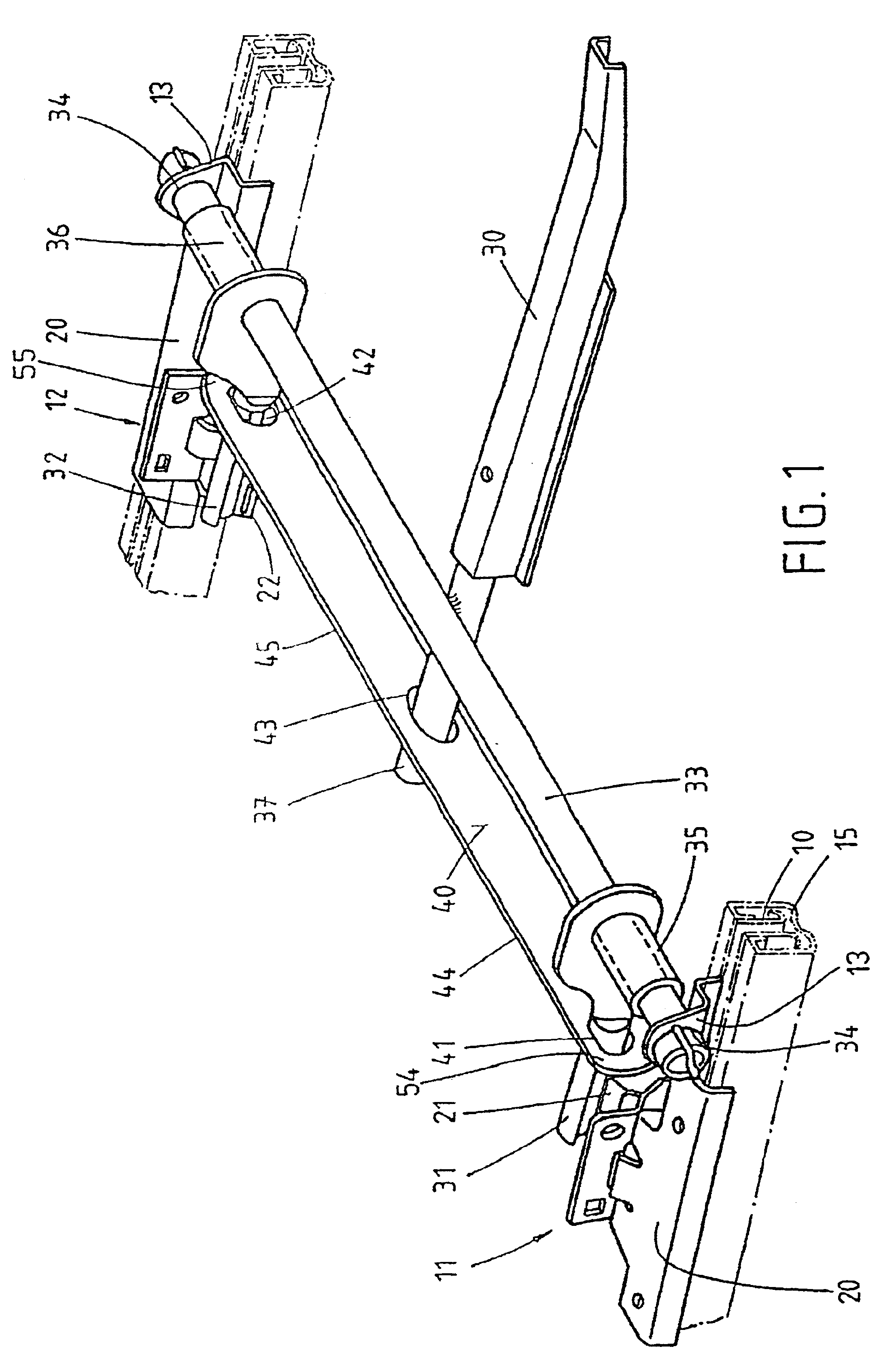
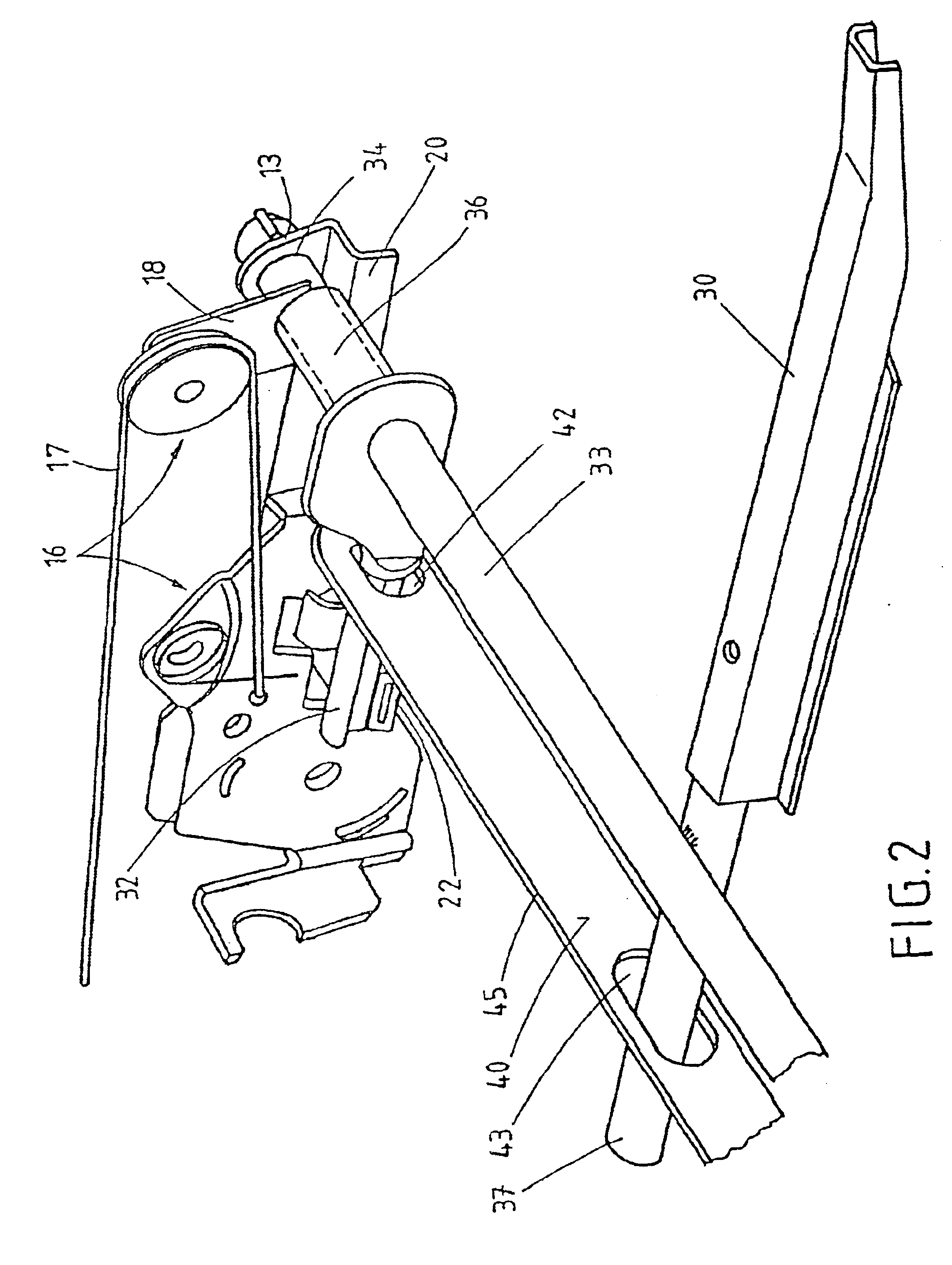
According to another embodiment, it is also favorable for the rods to be mounted on a transverse tube in such a way that they can both swivel and slide, because as a result it becomes possible to reduce the distance between the two rods when the compensating lever tilts. This swiveling and sliding arrangement prevents the rods from getting jammed on the transverse tube.
The functionality of the rods can be improved even more by mounting them on the transverse tube by way of support tubes, as a result of which the rods are supported on the transverse tube in a way which prevents them from tilting.
In another embodiment of the invention, additional rods are provided at the ends of the two support tubes which face the actuating element. The end of each of these rods passes through an opening in the end of the associated lever arm of the compensating lever and thus enters into a working connection with the compensating lever. AS a result of this measure, the length of the compensating lever can be reduced, and the lever thus acquires greater rigidity.
In another embodiment according to the invention, the differential is designed as a planetary gear system. In this case, the transverse tube is divided into two parts, and these two parts of the transverse tube represent the first and second takeoffs of the planetary gear system. The first takeoff is connected nonrotatably to one of the rods, whereas the second takeoff is connected nonrotatably to the second rod. The two takeoffs, i.e., the two parts of the transverse tube, are supported rotatably one inside the other, so that the two takeoffs are able to rotate relative to each other. The planetary gear system can consist of an internal gear, which is mounted nonrotatably on the one takeoff; a spur gear, which is attached nonrotatably to the second takeoff; and a planet wheel, also supported rotatably between the internal gear and the spur gear. This planet wheel can be supported on the actuating lever, which is itself supported rotatably on a takeoff (a part of the transverse tube) on the spur gear side. In this embodiment of the invention, the two rods can also be disconnected very reliably from each other without the need for a large amount of effort in terms of either material or production work.

Problems solved by technology

This is not possible with the known longitudinal adjustment device, because no provisions are made to allow for this overstroke.
The disadvantage here, however, is that the ability to compensate for manufacturing tolerances is available only on one of the rods of the actuating element.

Method used


Image

  • Longitudinal adjustment device for vehicle seats
  • Longitudinal adjustment device for vehicle seats
  • Longitudinal adjustment device for vehicle seats

Examples


Embodiment Construction

FIGS. 1-3c show the invention on the basis of a first exemplary embodiment. Not shown in these figures is the seat part, which is connected by a piece of known adjusting hardware to a seat back. The base frame of the seat part can be rigidly attached along its two long sides to the runner rails 10, shown in the figures, which are part of a rail assembly, one of which is provided along each long side of the seat. Each rail assembly comprises not only the runner rail 10 but also a guide rail 15, attached to the floor of the vehicle, in which the runner rail can slide in the longitudinal direction after a locking device 11, 12 has been released. The locking device 11, 12 is to be released by actuating components. These actuating components include in particular an actuating lever 30, which is rigidly connected to the transverse tube 33 and which is supported on the runner rails 10 by way of the transverse tube 33. In the present exemplary embodiment, one end 37 of this lever passes thr...


PUM


Abstract

The present invention pertains to a longitudinal adjustment device for vehicle seats, in which the seat is attached along each of its long sides to runner rails 10, mounted with freedom to slide in guide rails 15, which are attached to the vehicle. Each runner rail 10 has a locking device, which can be released from its connection to the guide rail 15. The locking device comprises a release lever 21, 22, supported with freedom to swivel on each runner rail 10, to move the device into its released position, which lever is to be shifted via rods 31, 32 of an actuating element 30 supported on the runner rails 10. The adjusting moment exerted on the actuating element 30 is transmitted to the rods 31, 32 via a differential, where the rods 31, 32 are disconnected from each other. As a result, each rod can be moved until the locking device has been moved completely into the position in which it is released.

Description

1. Field of the InventionThe invention pertains to a longitudinal adjustment device on a vehicle seat in which each side of the seat is attached to runner rails, which are mounted so that they are free to slide in guide rails attached to the vehicle, and where each runner rail has a locking device, which can be released from its connection to the guide rail, which locking device comprises a release lever supported with freedom to swivel on each runner rail for moving the device into its released position, this lever being shifted via rods of an actuating element supported on the runner rails.2. Description of the Related ArtA longitudinal adjustment device of the type indicated above is known from DE 198-27,068 C1, in which the ends of the release levers cooperating with the rods of the actuating element extend at an angle to the horizontal along the associated runner rails. The rods of the actuating element are supported in the bearing seats on the runner rails in such a way that t...

Claims


Application Information

Patent Timeline
IPC IPC(8): B60N2/08B60N2/06B60N2/07
CPCB60N2/0705B60N2/0715B60N2/0825B60N2/0868B60N2/0887B60N2/08
Inventor SCHULER, ROLFSTEMMER, JURGEN
Owner KEIPER GMBH & CO KG
Learn More