Control system for use with DBR lasers

Inactive Publication Date: 2004-02-24
AGERE SYST INC
View PDF6 Cites 17 Cited by
  • Summary
  • Abstract
  • Description
  • Claims
  • Application Information

AI Technical Summary

Problems solved by technology

Such a ramping of the current to the tuning section has the immediate undesirable effect of tending to shift the wavelength of the laser.
However, depending on the thermal response time of the system, the mitigating effect of the temperature compensation feedback loop (i.e., to reduce the shift in wavelength) is not always ideal.
Often, the wavelength has drifted farther than desired during the ramping of the tuning section current because the system cannot adequately re

Method used


Image

  • Control system for use with DBR lasers
  • Control system for use with DBR lasers
  • Control system for use with DBR lasers

Examples


Embodiment Construction

A preferred embodiment and application of the invention will now be described with reference to FIGS. 1-6. Other embodiments may be realized and structural or logical changes may be made to the disclosed embodiment without departing from the spirit or scope of the invention.

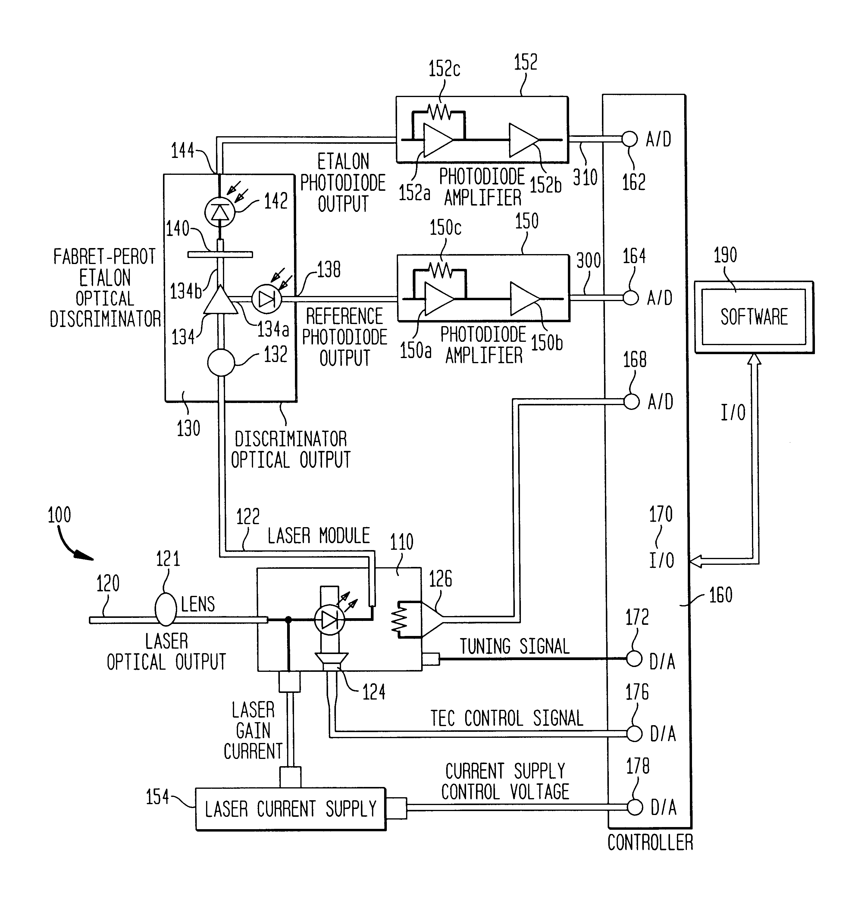
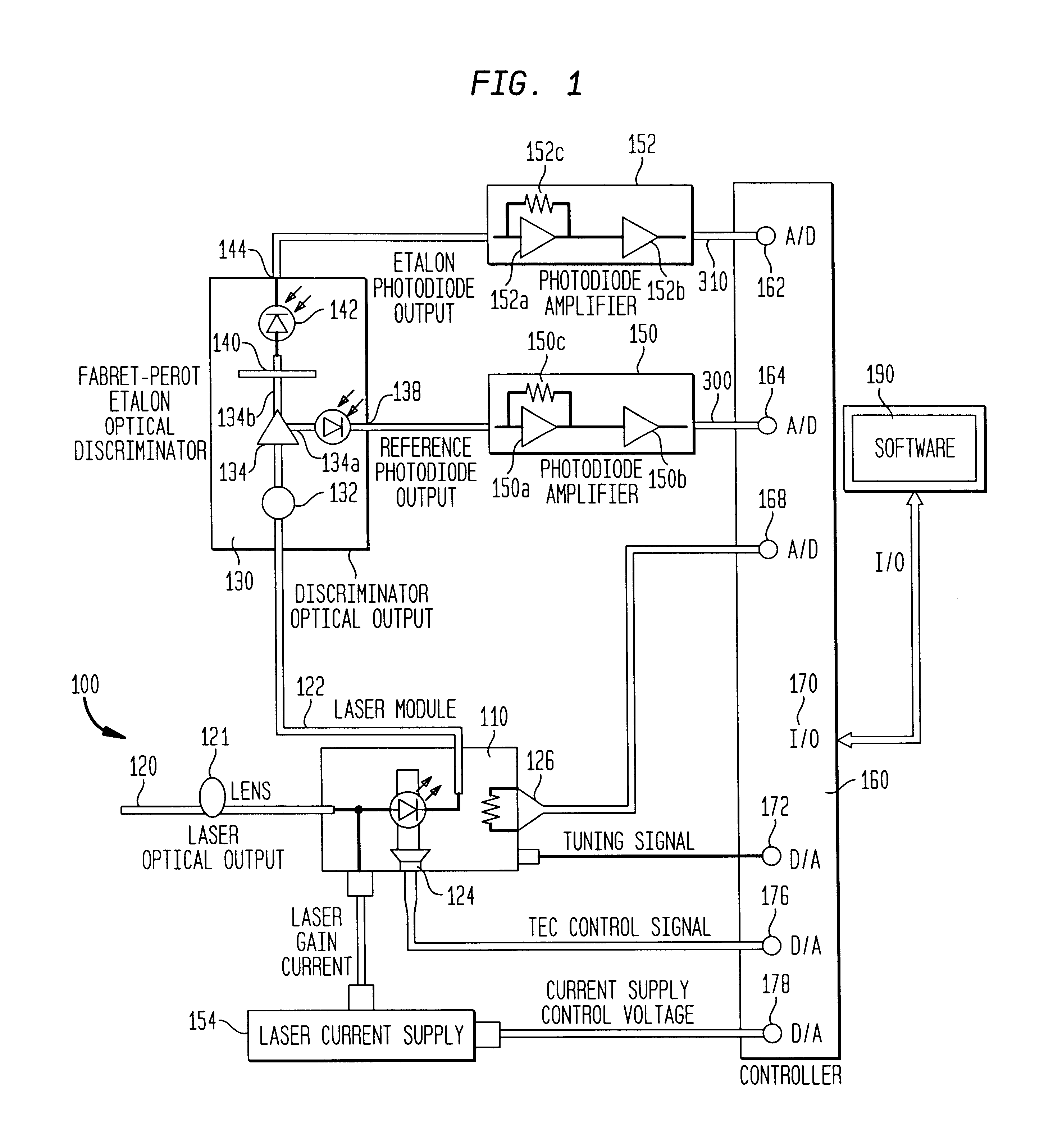
FIG. 1 illustrates a DBR laser control system in accordance with an embodiment of the present invention. A laser module 110 is mounted on a thermoelectric cooler (TEC) 124. As known in the art for temperature tuned lasers, the output of laser module 110 can be adjusted by modifying its temperature. The temperature of laser module 110 can be adjusted by varying the temperature of TEC 124. A thermistor 126 is used to monitor the temperature of the module 110. The temperature of TEC 124 is varied based on a TEC control signal from a controller 160 through a digital to analog (D / A) controller output 176.

Controller 160 may include a programmable logic device, one example being a microprocessor. If a microprocessor is ...


PUM


Abstract

The present invention provides a system and method for dynamically increasing the numeric gain applied to the temperature loop in a DBR laser control system in response to the anticipated wavelength change that occurs as a tuning current ramp is in progress. In accordance with a preferred embodiment of the invention, the feedback control signal to the laser's TEC is overcompensated for, and as a result, the system is forced to respond much faster, thermally, to the anticipated wavelength shift, thus providing improved real time wavelength stabilization to the control system. The implementation of the increased numeric gain can be carried out through software and/or firmware.

Description

1. Field of the InventionThe present invention relates to the field of tunable lasers. More specifically, it relates to a system and method for improving wavelength stabilization while also improving mode stabilization of DBR lasers.2. Description of the Related ArtOptical fiber communications systems provide for low loss and very high information carrying capacity. In practice, the bandwidth of optical fiber may be utilized by transmitting many distinct channels simultaneously using different carrier wavelengths. The associated technology is called wavelength division multiplexing (WDM).The wavelength bandwidth that any individual channel occupies depends on a number of factors, including the impressed information bandwidth, and margins to accommodate carrier frequency drift, carrier frequency uncertainty, possible inter-channel cross-talk due to non-ideal filters.To maximize the number of channels, lasers with stable and precise wavelength control are required to provide narrowly ...

Claims


Application Information

Patent Timeline
IPC IPC(8): H01S5/00H01S5/0687H01S5/042H01S5/06
CPCH01S5/042H01S5/0687H01S5/0612H01S5/0617
Inventor BROUTIN, SCOTT L.PLOURDE, JAMES K.STAYT, JOHN W.
Owner AGERE SYST INC
Why Eureka
Try Eureka