
Method and apparatus for performing parallel asynchronous testing of optical modules

a technology of optical modules and asynchronous testing, applied in the field of parallel asynchronous testing of optical modules, can solve the problems of inefficient serial assembly and testing, difficult challenges not faced by electronic equipment manufacturers, and inefficient deployment of production lines or testing stations to specific modules or components

Inactive Publication Date: 2004-02-24
CIENA
View PDF12 Cites 33 Cited by
  • Summary
  • Abstract
  • Description
  • Claims
  • Application Information

AI Technical Summary

Benefits of technology

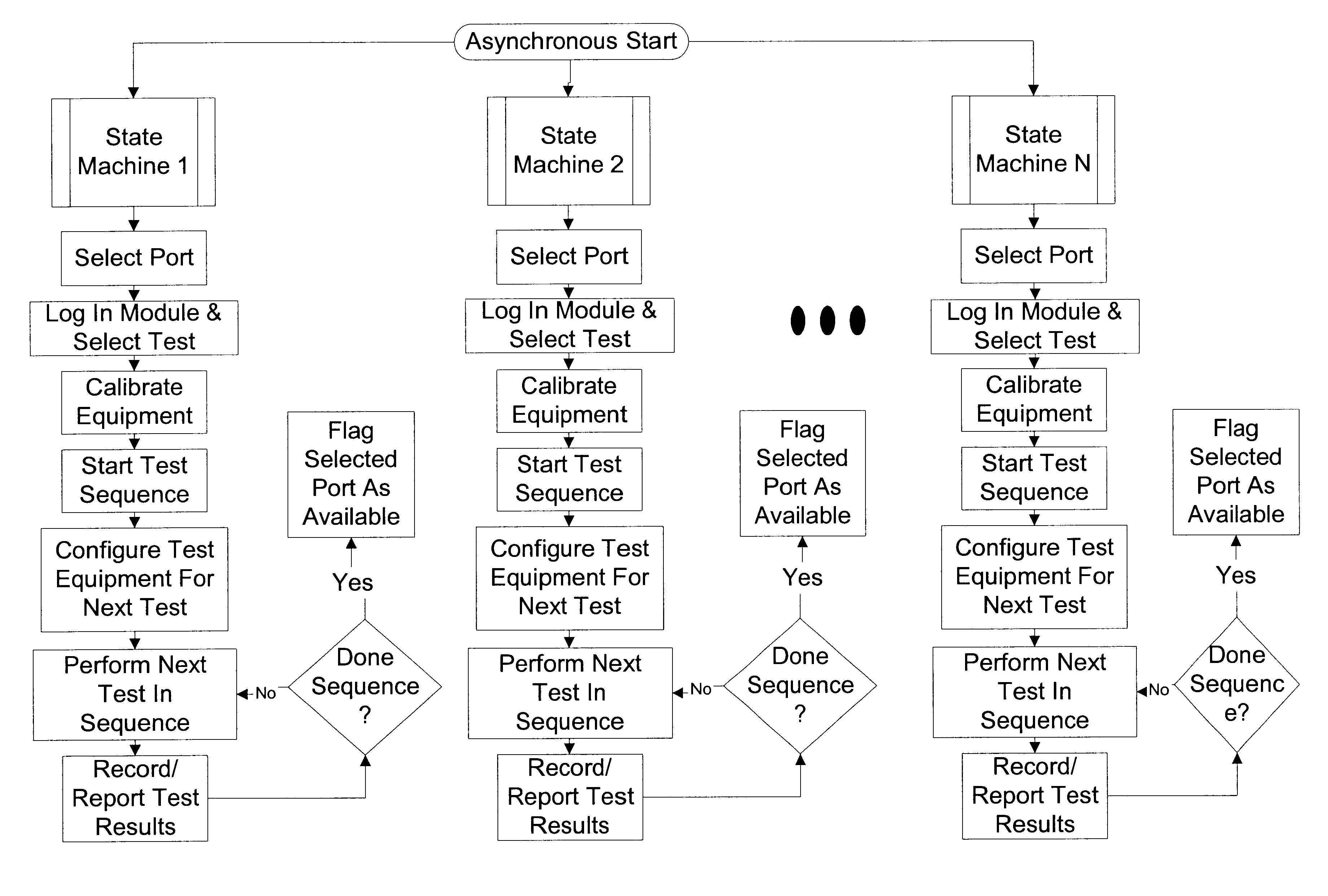
The invention is a system and method for testing and calibrating optical and electro-optical modules in a parallel, asynchronous manner. The system includes a controller and multiple state machines that determine if a testing process or instrument is available for a selected module and initiate the testing process or instrument asynchronously. The system can adapt to changes in the mix of components being manufactured and can be used in a high-mix environment. The technical effects of the invention include improved efficiency and flexibility in testing and calibration of optical modules, reduced labor resources, and improved utilization of test equipment.

Problems solved by technology

Optical networking equipment manufacturing presents difficult challenges not faced by electronic equipment manufacturers.
Furthermore, the orders are often unpredictable and sporadic which means that the manufacturing must be highly adaptable and dynamic.
Thus, it is inefficient to dedicate a production line or testing station to a particular module or component.
Such serial assembly and testing is inefficient and labor intensive.
As such, the typical test station is not flexible and leads to inefficient utilization of test equipment and labor resources.
Furthermore, the high mix environment faced by optical networking equipment manufacturers makes using a parallel testing architecture inadequate since different tests needs to be performed on the high mix of components.

Method used


Image

  • Method and apparatus for performing parallel asynchronous testing of optical modules
  • Method and apparatus for performing parallel asynchronous testing of optical modules
  • Method and apparatus for performing parallel asynchronous testing of optical modules

Examples


Embodiment Construction

The following detailed description of the invention refers to the accompanying drawings. The same reference numbers in different drawings identify the same or similar elements. Also, the following detailed description does not limit the invention. Instead, the scope of the invention is defined by the appended claims and equivalents thereof.

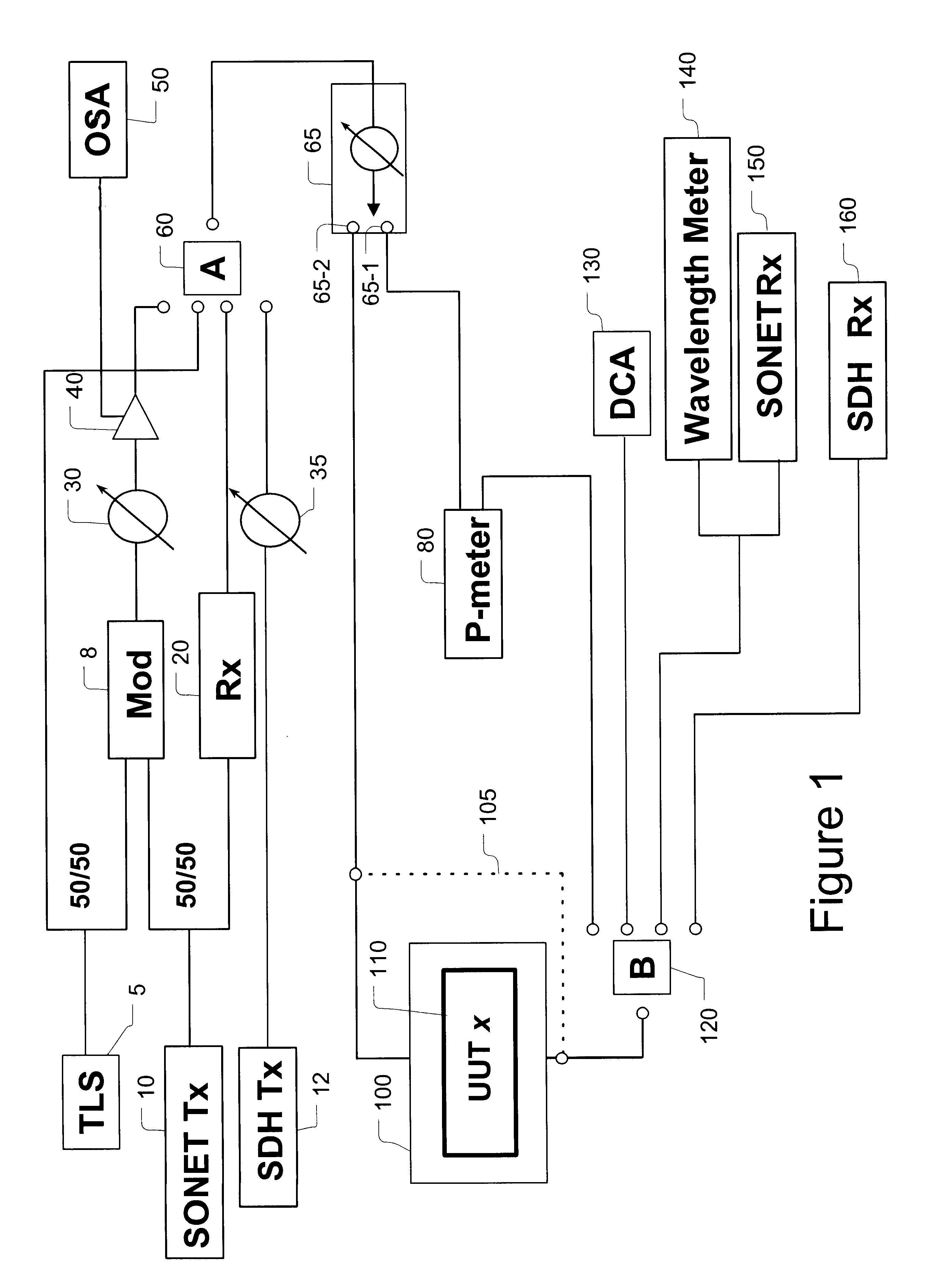
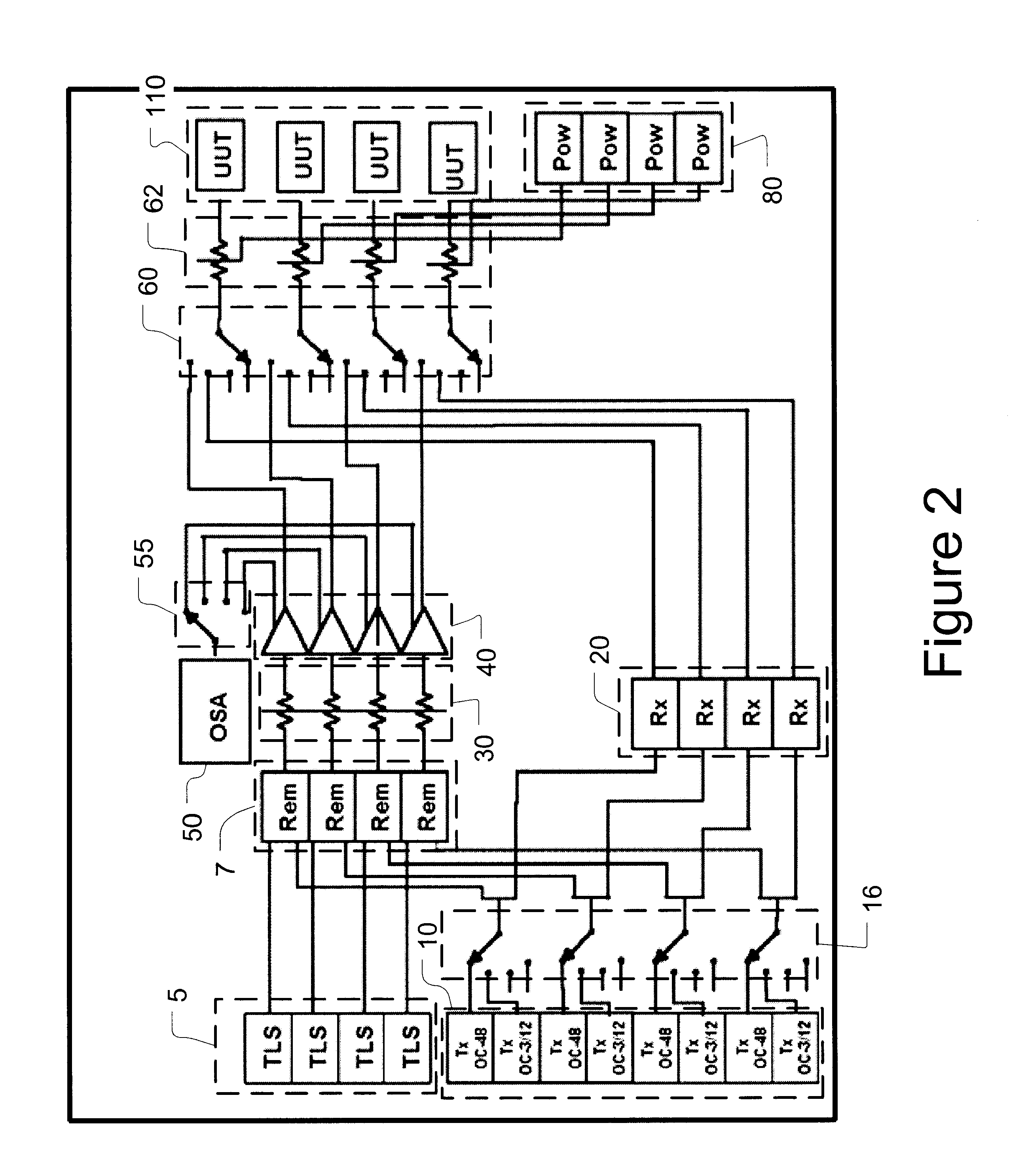
The expression "optically communicates" as used herein refers to any connection, coupling, link or the like by which optical signals carried by one optical system element are imparted to the "communicating" element. Such "optically communicating" devices are not necessarily directly connected to one another and may be separated by intermediate optical components or devices.

Furthermore, the term "connection" and "operative connection" as used herein is a relative term and does not require a direct physical connection. For example, controller 70 may communicate with other elements by using a communication pathway over a fiber span, an Internet conne...


PUM

PropertyMeasurementUnit
wavelengthsaaaaaaaaaa
optical testsaaaaaaaaaa

Abstract

A method and apparatus for performing parallel asynchronous testing of a plurality of optical modules utilizes state machines that may be implemented in a common controller. Desired optical tests are selected by an operator. The invention determines if a testing process or instrument required for the selected optical tests is available. A COM port may also be locked for each of the selected optical tests from among a plurality of COM ports to prevent interference between different tests. By reserving resources such as COM ports and testing instruments in this fashion the invention may asynchronously initiate execution of the selected optical tests. If a resource such as a COM port, testing process or instrument is not currently available, the test is place in COM port and testing queues to await availability of that resource. Once a test is completed, the resource is unlocked so that one of the state machines may asynchronously initiate another test. Various displays are generated so that an operator may view the progress of each of the tests. A database is utilized to store test results as well as test recipes and test instrument drivers that aid in the control of a testing architecture.

Description

1. Field of InventionThe invention generally relates to testing and calibration of optical and electro-optical modules, generically referred to herein as "modules" or "optical modules." More specifically, the invention relates to systems, apparatuses and methods for performing parallel, asynchronous testing and calibration of optical and / or electro-optical modules.2. Description of Related ArtElectronic manufacturers that produce large volumes of identical components have sought to improve widely-used serial testing techniques by employing parallel testing schemes. Such parallel test schemes subject a large number of identical electronic devices to the same test. The test cycle for such electronic components is relatively short and the testing of a plurality of such components is initiated simultaneously. In other words, there is known a synchronous, parallel testing scheme for testing electronic components.Optical networking equipment manufacturing presents difficult challenges not...

Claims


Application Information

Patent Timeline
Patent Type & Authority Patents(United States)
IPC IPC(8): G02F1/00H04B10/08H04Q11/04
CPCH04B10/07H04J2203/0062
Inventor COIN, BRYANRANSFORD, MICHAEL J.SCHWARTEN, DAVID A.JIANG, CHAODAR, IQBAL M.CSIPKES, ANDREI
Owner CIENA
Learn More