Cam mechanism for translation of circular motion into reciprocal motion

a technology of circular motion and cam mechanism, which is applied in the direction of hoisting equipment, gearing, other domestic objects, etc., can solve the problem of higher assembly cos

Inactive Publication Date: 2004-03-02
DELTA KOGYO CO LTD +1
View PDF35 Cites 51 Cited by
  • Summary
  • Abstract
  • Description
  • Claims
  • Application Information

AI Technical Summary

Problems solved by technology

This makes the a...

Method used


Image

  • Cam mechanism for translation of circular motion into reciprocal motion
  • Cam mechanism for translation of circular motion into reciprocal motion
  • Cam mechanism for translation of circular motion into reciprocal motion

Examples


first embodiment

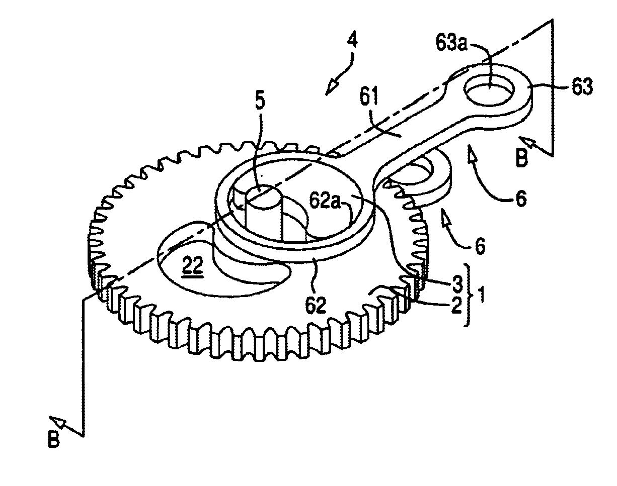
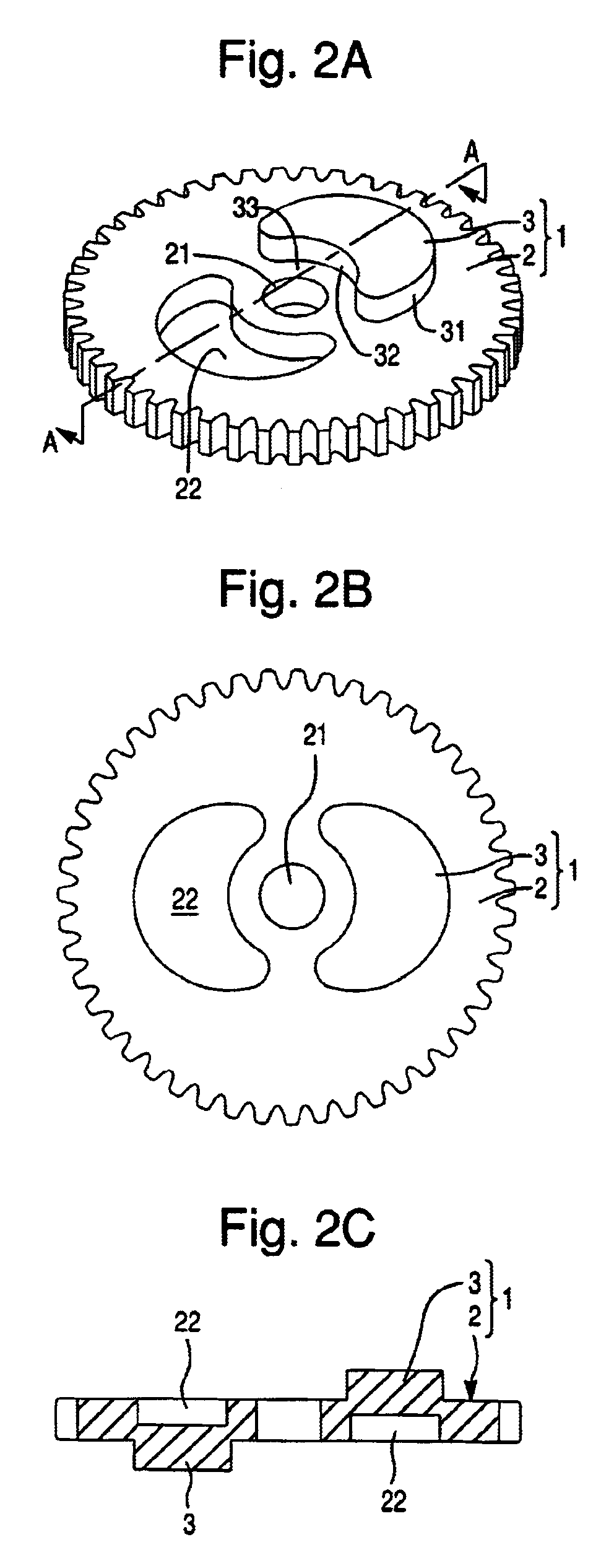
FIGS. 2A, 2B, 2C show a cam mechanism according to the present invention. FIG. 2A is a perspective view of the cam mechanism, and FIG. 2B is a plan view thereof, and FIG. 2C is a sectional view thereof taken along the lines A. As shown in FIGS. 2A-2C, the cam mechanism 1 comprises a spur gear 2 having a plurality of gear tooth in the predetermined pitch, and a pair of eccentric cams 3 each protruded from the surface and the back of the spur gear 2. The spur gear 2 has a shaft hole 21 at the center. The inner surface of the shaft hole 21 is slidably fitted on a central shaft 5 which will be described later to rotatively support the spur gear 2 around the central shaft 5.

The eccentric cam 3 has an inscribed surface 31 inscribed in the circular locus having the center and diameter set to include the shaft hole 21, and a surface facing to the shaft hole 21 that is an opposing surface 32 opposing to the surface of the central shaft 5. The opposing surface 32 in the present embodiment is ...

second embodiment

According to the cam mechanism 4a of the second embodiment, when the eccentric cam 3 rotates around the central shaft 5 to perform the crank motion, since the sliding ring 51 rotates around the central shaft 5, the crank motion of the output rod 6 can smoothly be performed.

FIG. 7 is a perspective view showing a main part of a mowing machine utilizing the above-described cam apparatus according to one embodiment of the present invention. FIG. 8 is a sectional view of FIG. 7. FIG. 7 shows the back of the mowing machine upward and FIG. 8 shows the back of the mowing machine downward. In the present embodiment, the cam apparatus 4 of the first embodiment is utilized. In FIGS. 7 and 8, the mowing machine 7 comprises a casing 71 containing the cam apparatus 4, a cover 72 placed at the bottom of the body for closing the opening of the casing 71, a pair of blades that are mowing blade members and that are connected to the cam apparatus 4 in the casing 71, and a driving mechanism which is no...


PUM


Abstract

A cam mechanism for use in a mowing machine. The cam mechanism is comprised of a spur gear and protruding eccentric cams from the top and bottom surfaces of the spur gear. The cam mechanism is formed from a half blanking press process. The eccentric cams are symmetrically formed around a shaft hole located in the center of the spur gear. Members with a hole equaling that of the eccentric cam and shaft hole point symmetry are then fitted onto the eccentric cam. The members are then capable of reciprocation with a phase differential of 180 degrees of each other. The concave portion of the eccentric cam permits lubricants to be filled in the space facilitating the smooth operation of the cam mechanism.

Description

1. Field of the InventionThe present invention relates to a cam mechanism in which a cam is protruded from the surface and / or back of a gear, a cam apparatus utilizing the cam mechanism, and a mowing machine utilizing the cam apparatus.2. Description of Related ArtConventionally, a cam mechanism for converting the circular motion to the reciprocating motion is shown in FIG. 1A and FIG. 1B is known. The cam mechanism 100, as shown in FIG. 1A, comprises a gear 110 and a circular cam 120 fixed on the eccentric position of the gear 110. The gear 110 has a central hole 111 formed at the central position, and the circular cam 120 has an eccentric hole 121 having the same diameter as the diameter of the central hole 111 at the eccentric position. The circular cam 120 piles on the gear 110 and they are fixed together so that the center of the hole 111 is aligned to the center of the hole 121.The circular cam 120 has two through holes 122 in the appropriate positions, and the gear 110 has sc...

Claims


Application Information

Patent Timeline
IPC IPC(8): B21D53/26B21D53/28F16H21/00F16H21/18A01G3/08F16H53/00
CPCB21D53/28F16H21/18Y10T74/2101Y10T74/19898
Inventor AKEHI, YOUSONOMURA, FUMIO
Owner DELTA KOGYO CO LTD
Why Eureka
Try Eureka