Method and impact machine for forming a body

a technology of impact machine and body, which is applied in the direction of forging hammers, press, shaping presses, etc., can solve the problems of large risk of failure, large loss of energy in stands and foundations, and large loss of all joints, so as to reduce the risk of failure, and reduce the loss of energy.

Inactive Publication Date: 2004-03-02
MORPHIC TECH
View PDF14 Cites 21 Cited by
  • Summary
  • Abstract
  • Description
  • Claims
  • Application Information

AI Technical Summary

Benefits of technology

The lower velocities thus improve the possibility to synchronize the movements of the movable units during the impact operation. Even though the velocities are radically reduced, the forming work nevertheless can be perfect, whether the working material is a powder or a solid body. Without binding the invention to any specific theory, it can be assumed that this is due to the good synchronization of the counter directed movements, which in turn has the result that the kinetic energy of the movable masses essentially can be used as effective forming work with small losses of energy to the machine foundation and stand.
Another favourable effect with the lower velocities of the movements that are movable towards one another, is that the ram travels can be shortened. This makes it possible t

Problems solved by technology

The dynamic forces of short duration which are generated at the ram impact and which in impact machines of prior art are conveyed around in the system via stand and foundation may be several thousand times larger than in conventional presses and imply that considerable amounts of energy are lost in stands and foundations instead of being used for effective work at an optimal way.
The stress on all joints the

Method used


Image

  • Method and impact machine for forming a body
  • Method and impact machine for forming a body
  • Method and impact machine for forming a body

Examples


Embodiment Construction

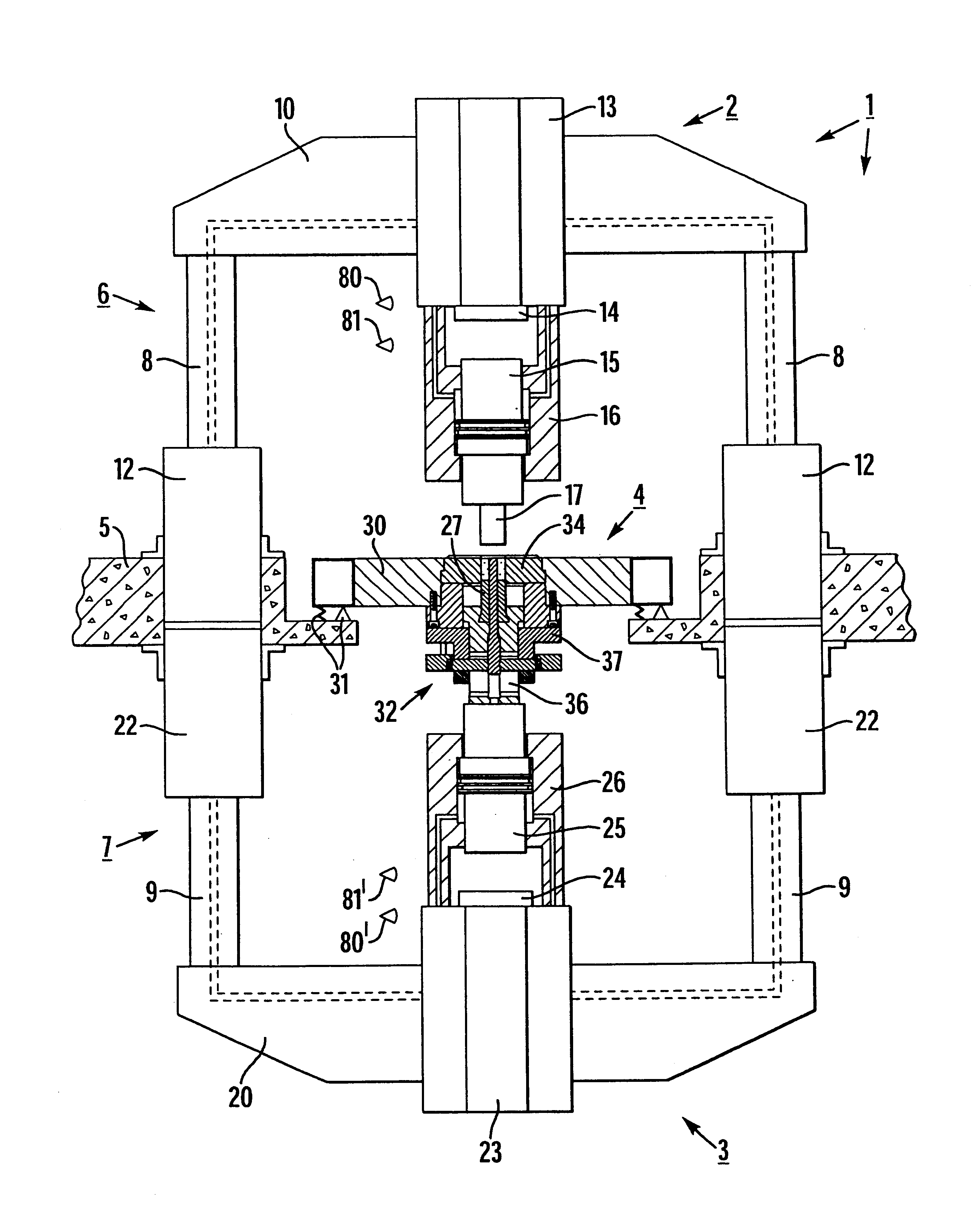
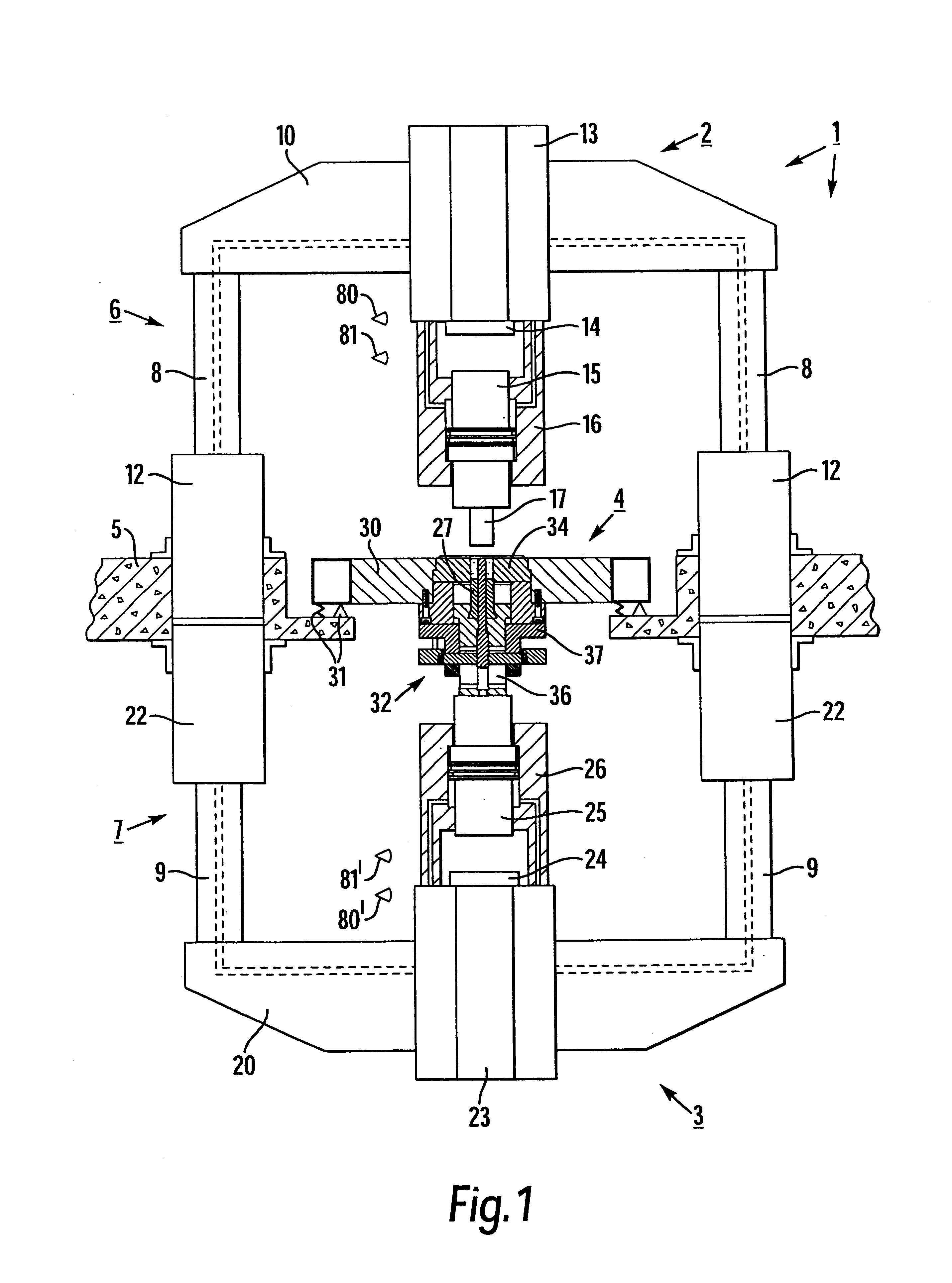
With reference first to FIG. 1, an impact machine is generally designated 1. Its main parts consist of an upper impact unit 2, a lower impact unit 3, a central unit 4, an upper stand 6 consisting of two upper rods 8, which consist of a pair of piston rods, and a lower stand 7 consisting of a pair of lower rods 9, which also consist of a pair of piston rods. A foundation or base is designated 5.

The upper impact unit 2 comprises a yoke 10 on the piston rods 8, which yoke can be raised and lowered by means of two upper, hydraulic lifting cylinders 12, which are united with the base 5, the hydraulic chambers of which are filled with and drained of hydraulic fluid via hydraulic conduits which extend through the piston rods 8 and the yoke from and to a pressure source and a tank, respectively. The yoke 10 carries an upper hydraulic impact cylinder 13, which is connected with the yoke, said impact cylinder containing an upper ram in the form of an impact piston 14. An upper impact body is ...


PUM

PropertyMeasurementUnit
Momentumaaaaaaaaaa
Lengthaaaaaaaaaa
Pressureaaaaaaaaaa

Abstract

A method of forming a body of a formable working material in an impact machine, which comprises an upper impact unit (29 with an upper ram (14), an upper punch (17), a lower impact unit (3) with a lower ram (24), a lower punch (27), and mould cavity for the working material between the punches when the punches are brought towards one another, is characterized in that downwards movable masses, which comprise at least the mass of the upper ram and the mass of the upper punch, and upwards movable masses, which include at least the mass of the lower ram and the mass of the lower punch, are caused to move towards one another and towards the working material in the mould cavity, that the masses which move downwards, including the upper punch (17) obtain a downwards directed velocity (v1) and those masses which move upwards, including the lower punch (27), obtain an upwards directed velocity (v2), wherein the movable parts have such masses and the velocities are so high that the momentums of the downwards movable masses and the upwards movable masses become essentially equally large, i.e. so that the following condition applies.where m1 is the total mass of the downwards movable masses during the stroke, and m2 is the total mass of the upwards movable masses during the stroke.

Description

The invention relates to a method of forming a body of a formable working material in an impact machine, which comprises an upper impact unit with an upper ram, an upper punch, a lower impact unit with a lower ram, a lower punch, and a mould cavity for the working material between the punches when the punches are brought towards one another. The invention also relates to an impact machine for the carrying out of the method.Impact machines for working by the employment of high kinetic energy are machines for working in the first place metal, such as cutting, punching, and plastic forming of powder-components, powder compaction, and similar operations, in which the speed of a ram, which may consist of a press piston, may be essentially higher than in conventional presses. Also polymeric and ceramic working materials can be conceived, as well as various composites of metals, polymers and ceramic materials. The working principle is based on the development of a very high kinetic energy ...

Claims


Application Information

Patent Timeline
IPC IPC(8): B22F3/17B22F3/00B22F5/00B21J5/00B21J7/34B21J7/00B21J5/02B30B11/02
CPCB21J5/02B21J7/00B21J7/34B22F3/17B22F5/00B30B11/027B22F3/02B22F3/10B22F3/164B22F2998/10B22F2999/00B22F2003/202
Inventor OLSSON, H.ANG.KAN
Owner MORPHIC TECH
Why Eureka
Try Eureka