Drive unit with an electric machine

Inactive Publication Date: 2004-03-02
MANNESMANN SACHS AG
View PDF12 Cites 45 Cited by
  • Summary
  • Abstract
  • Description
  • Claims
  • Application Information

AI Technical Summary

Problems solved by technology

The resulting rise in the combustion pressures increases the mechanical power output but also leads to the situation that, unless structural countermeasures are taken, the crankshaft is subjected to increased flexural vibrations.
During the operation of an internal combustion engine, therefore, the problem occurs that the rotor of an electric machine in effective connection with the crankshaft executes a wobbling motion.
The slewing motion of the rotor is therefore superimposed on the rotational motion of the rotor, and thus the coaxial relationship between the rotor and the stator is impaired.
This means that the radial dimension of the air gap of the electric machine is subject to continuous fluctuation as the crankshaft turns, which results in a considerable loss of efficiency and to va

Method used


Image

  • Drive unit with an electric machine
  • Drive unit with an electric machine
  • Drive unit with an electric machine

Examples


Embodiment Construction

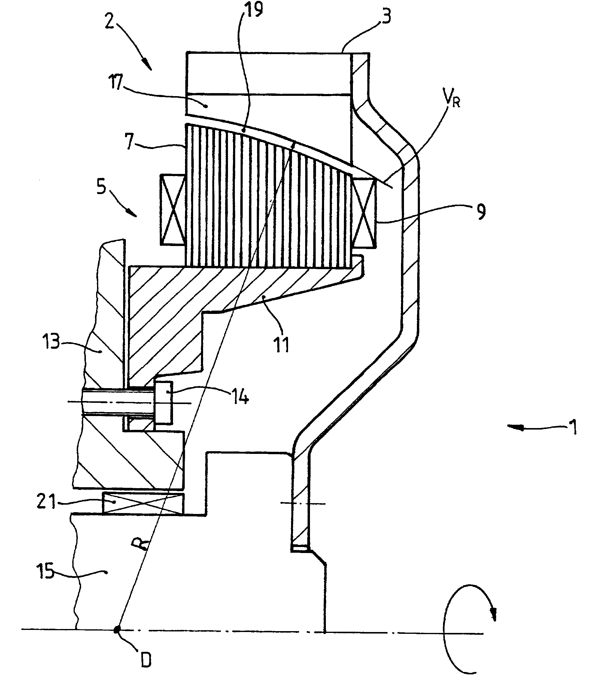
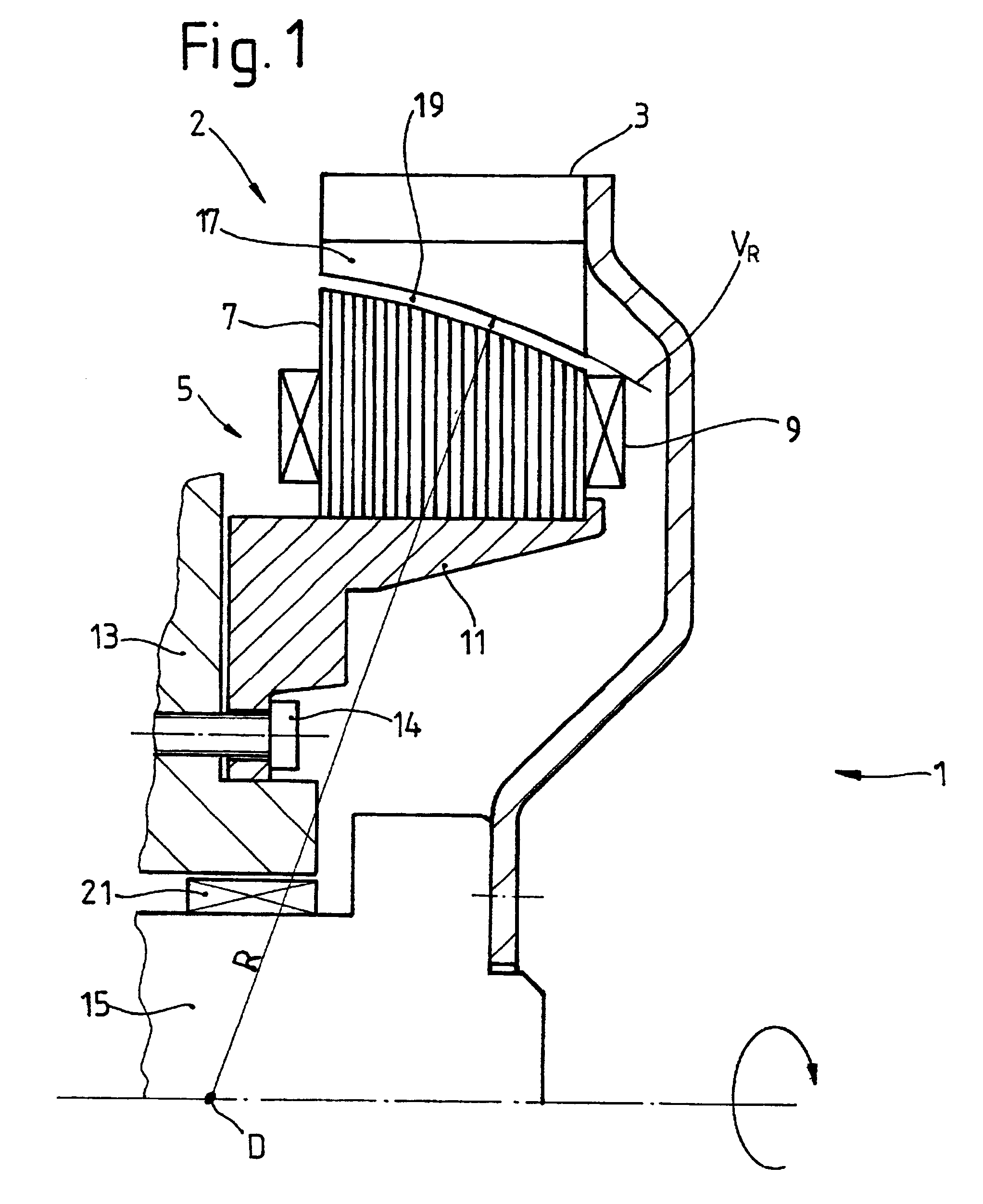
FIG. 1 is a schematic, sectional diagram of an electric machine 2 with a rotor 3 and a stator 5, which machine serves as part of a drive unit 1. The stator 5 consists of a stack of plates 7 with coils 9 mounted on it. The stack of plates is mounted on a stator flange 11, which, on the housing side, is attached by fastening means 14 to the housing 13 of an internal combustion engine serving as the drive element. It is also possible, however, for the stack of plates to be attached to a power takeoff element such as a transmission or a torque converter. The rotor 3 of the electric machine 2 surrounds the stator 5 radially on the outside and is connected to a drive shaft 15 of the internal combustion engine for rotation in common. The rotor 3 has permanent magnets 17 arranged around the circumference, which are opposite the coils 9. The intermediate space forms an air gap 19, extending in the radial direction, with a height which is constant within the scope of manufacturing and assembl...


PUM


Abstract

A drive unit with a drive and an electric machine, the drive being equipped with a drive shaft and the electric machine with a stator and a rotor. The rotor is coaxial to the stator and connected to the drive shaft for the transmission of torque, where the stator and the rotor interact with each other across an air gap, and where the drive shaft causes the rotor to execute a wobbling motion. In a cross section parallel to the drive shaft, the geometric course of at least one of the two surfaces forming the boundaries of the air gap, i.e., the surface of the rotor or the surface of the stator, is designed so that it at least approximates the geometric slowing curve (VR) described by the wobbling motion of the rotor.

Description

1. Field of the InventionThe invention pertains to a drive unit with a drive and an electric machine, the drive being equipped with a drive shaft and the electric machine with a stator and a rotor, the rotor being coaxial to the stator and in effective torque-transmitting connection with the drive shaft, where the stator and the rotor interact with each other across an air gap, and where the drive shaft causes the rotor to execute a wobbling motion.2. Description of the Related ArtDrive units of this type are known from, for example, the area of motor vehicle technology, where an internal combustion engine is combined with an electric machine to form a hybrid drive or where the electric machine is provided as a starter-generator. The electric machine can operate as a motor for starting the internal combustion engine or serve alone or in cooperation with an internal combustion engine to drive the vehicle. When the electric machine is operating as a generator, it can supply power to t...

Claims


Application Information

Patent Timeline
IPC IPC(8): B60K6/00B60K6/04H02K1/06H02K1/27H02K7/18H02K21/22H02K1/18B60K6/26B60K6/40B60K6/485H02K1/22
CPCB60K6/26B60K6/40B60K6/485H02K1/06H02K1/2786H02K7/1815B60L3/0061B60L11/14H02K21/222B60L2220/14Y02T10/6226Y10S903/951Y10S903/906B60L2210/40B60L50/16Y02T10/62Y02T10/64Y02T10/72Y02T10/7072H02K1/2791Y02T10/70
Inventor GEIGER, MARTINSCHIERLING, BERNHARD
Owner MANNESMANN SACHS AG
Why Eureka
Try Eureka