

Base station apparatus and method for suppressing peak electric power
a technology of base station and peak power, applied in the field of base station apparatus and method for suppressing peak power, can solve the problems of increasing the scale of the circuit, the transmission amplitude at a peak time becomes very high in comparison with an average amplitude, and the increase of the electric power consumption of the circuit, so as to achieve the effect of suppressing the peak power
- Summary
- Abstract
- Description
- Claims
- Application Information
AI Technical Summary
Benefits of technology
Problems solved by technology
Method used
Image

Examples
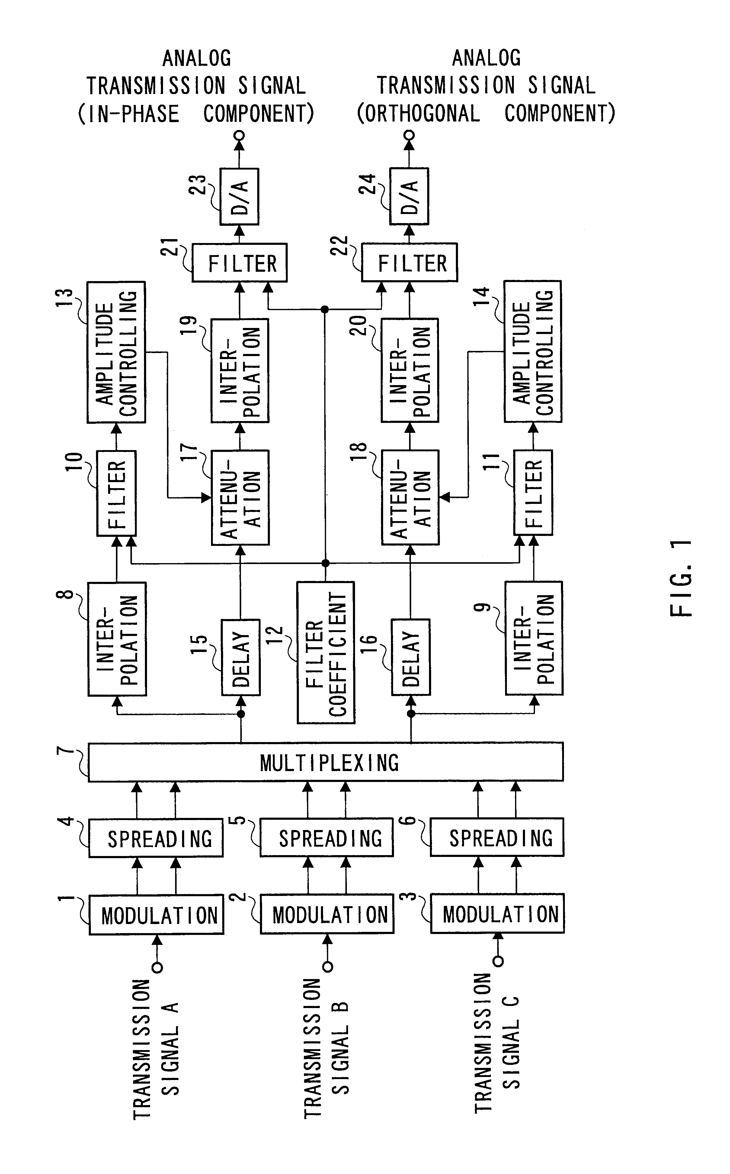
embodiment 1
FIG. 2 is a block diagram showing the structure of a base station according to the present invention.
In FIG. 2, a modulation section 101 performs the QPSK modulation of a transmission signal A to be transmitted to a user A, and outputs an in-phase component and an orthogonal component of the signal after the modulation to a spreading section 104. Similarly, a modulation section 102 performs the QPSK modulation of a transmission signal B to be transmitted to a user B, and outputs an in-phase component and an orthogonal component of the signal after the modulation to a spreading section 105. A modulation section 103 performs the QPSK modulation of a transmission signal C to be transmitted to a user C, and outputs an in-phase component and an orthogonal component of the signal after the modulation to a spreading section 106.
The spreading section 104 performs spread processing in which a peculiar spreading code is multiplied to the transmission signal A modulated in the QPSK modulation,...
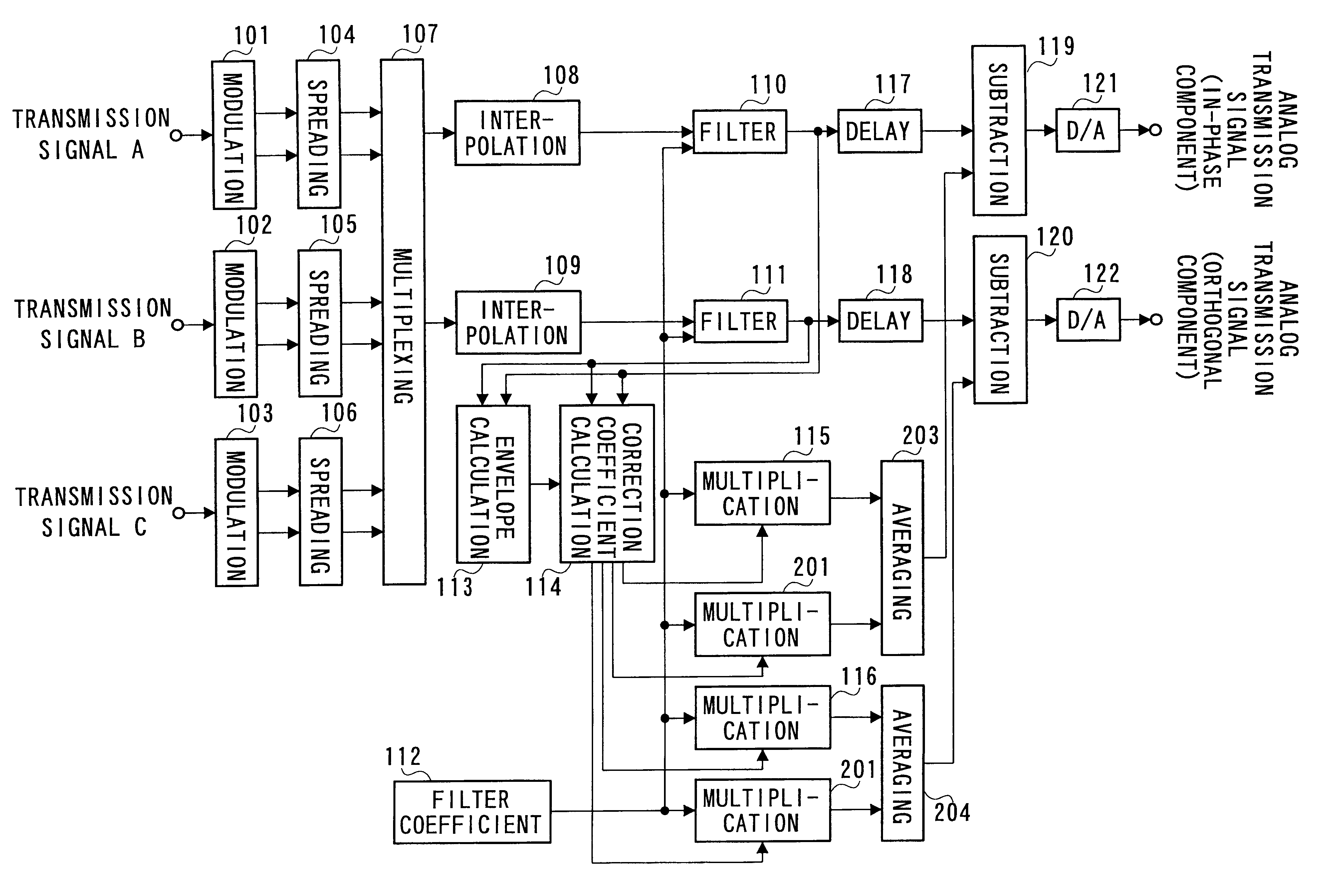
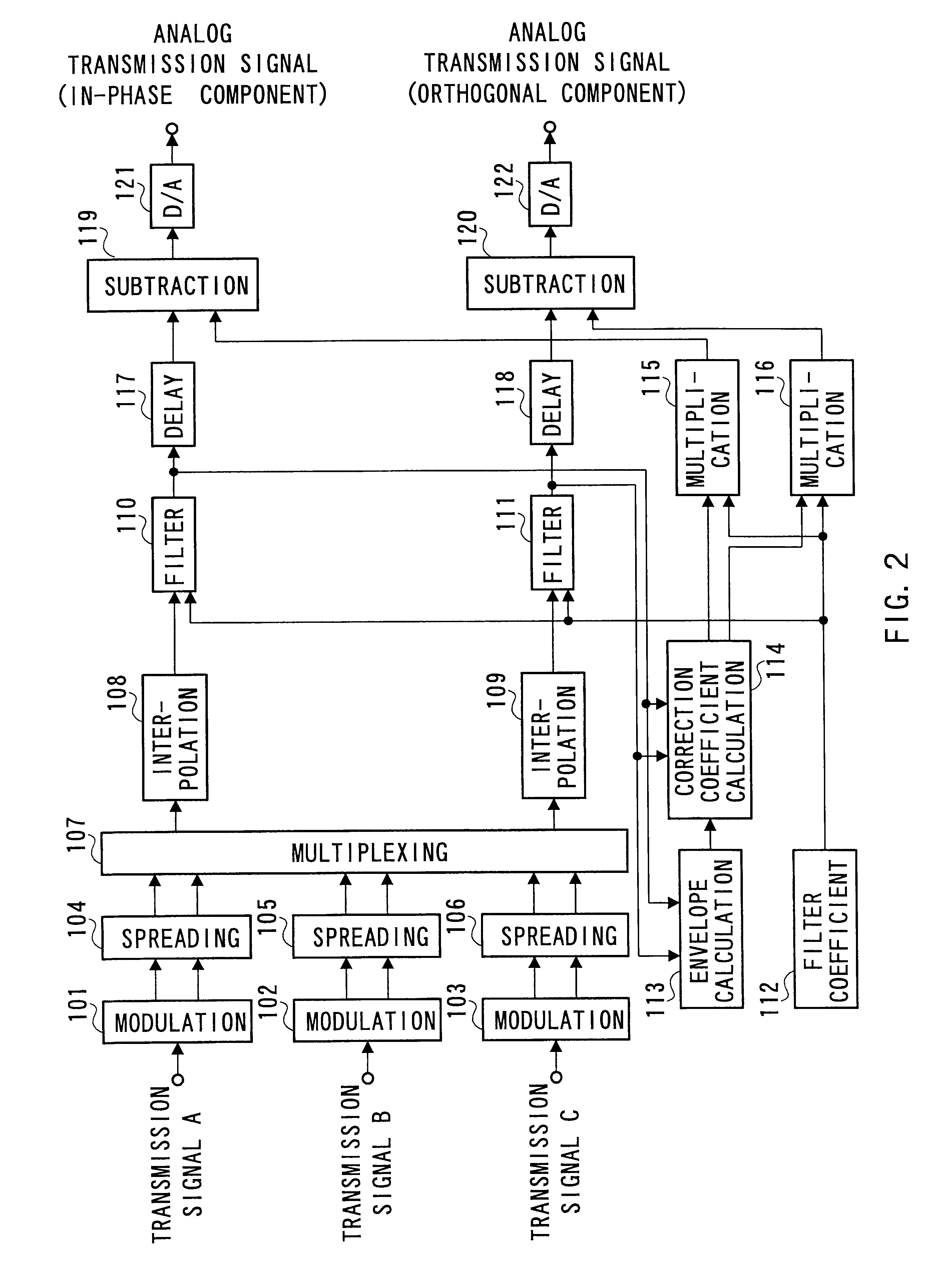
embodiment 2
FIG. 4 is a block diagram showing the structure of a base station according to the embodiment 2 of the present invention. Incidentally, the components in FIG. 4 similar to those in FIG. 2 are designated by the same reference numerals as those in FIG. 2, and their descriptions are omitted. The base station shown in FIG. 4 has a structure including multiplication sections 201 and 202 and averaging sections 203 and 204 in addition to the components of the base station shown in FIG. 2.
When the amplitude of a transmission signal calculated by the envelope calculation section 113 is beyond a permissible amplitude value, the correction coefficient calculation section 114 calculates the difference between the amplitudes of the transmission signal before and after the time, and performs the comparison of the largeness between the absolute value of the difference and a threshold value set previously.
When the absolute value is not beyond the threshold value, the correction coefficient calculat...
PUM
 Abstract
Description
Claims
Application Information