
Seismic prospecting method and device using simultaneous emission of seismic signals obtained by coding a signal by pseudo-random sequences

Inactive Publication Date: 2004-03-09
INST FR DU PETROLE
View PDF7 Cites 106 Cited by
  • Summary
  • Abstract
  • Description
  • Claims
  • Application Information

AI Technical Summary

Problems solved by technology

The necessary emission interruptions during a relatively long listening time interval have the effect of limiting the energy transmitted.
The use, in land seismic prospecting, of vibrators emitting simultaneously or insufficiently separated in time has drawbacks linked with various factors: the autocorrelation noise, the harmonics and the slow waves.
In the case of a frequency slip sweep, recording is semi-continuous and the bounces of the great values are found in front and behind, and they can interfere with the low values of the deep reflections of the previous shot if the slip time is insufficient.
If the time interval between the start of two successive shots decreases, there is a risk the slowest waves of a shot, air waves and surface waves, may be found on the next shot.

Method used


Image

  • Seismic prospecting method and device using simultaneous emission of seismic signals obtained by coding a signal by pseudo-random sequences
  • Seismic prospecting method and device using simultaneous emission of seismic signals obtained by coding a signal by pseudo-random sequences
  • Seismic prospecting method and device using simultaneous emission of seismic signals obtained by coding a signal by pseudo-random sequences

Examples


example

Consider five vibrators vibrating simultaneously with SBLM sequences of 2.sup.10 -1=1023 terms modulating a 60 Hz carrier and deduced from one another by time lag and circular permutation. The length of the sequence is thus ##EQU4##

seconds. The listening time will correspond (to within some carrier periods) to one fifth of the length of the sequence, i.e. ##EQU5##

seconds. The length of the (simultaneous) vibration of the vibrators will be 17 seconds. The correlation signal will have the length as follows: 17+2.times.3.4=23.8s.

Minimum Correlation Sequences

If a correlation noise of --30 dB is accepted, it is possible to use for example an emission device comprising 4 lines of 5 vibrators each, vibrating simultaneously and controlled by a 34-s sequence, for a listening time of 6.8 s. On a first line, the vibrators vibrate simultaneously or not, with the same sequence modified by a suitable time lag as described. The next vibrator lines are controlled by sequences belonging to the set o...


PUM


Abstract

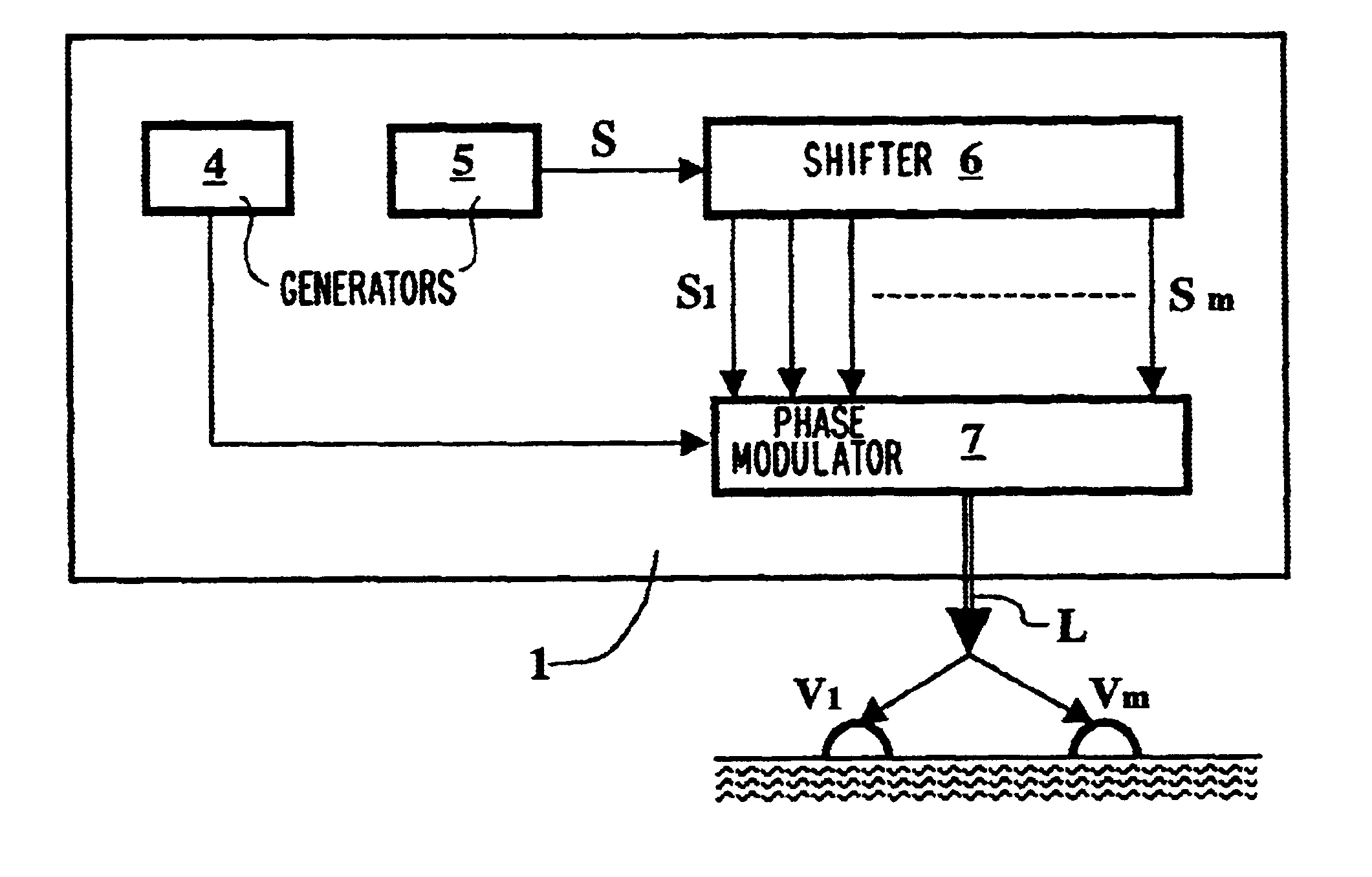
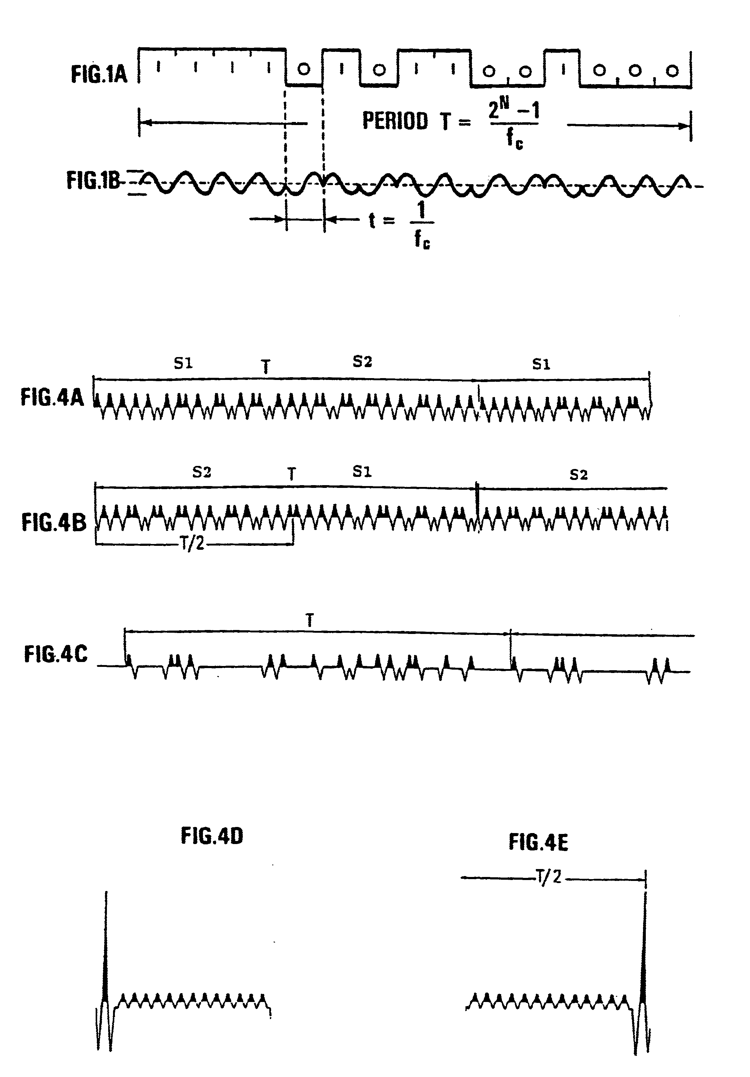
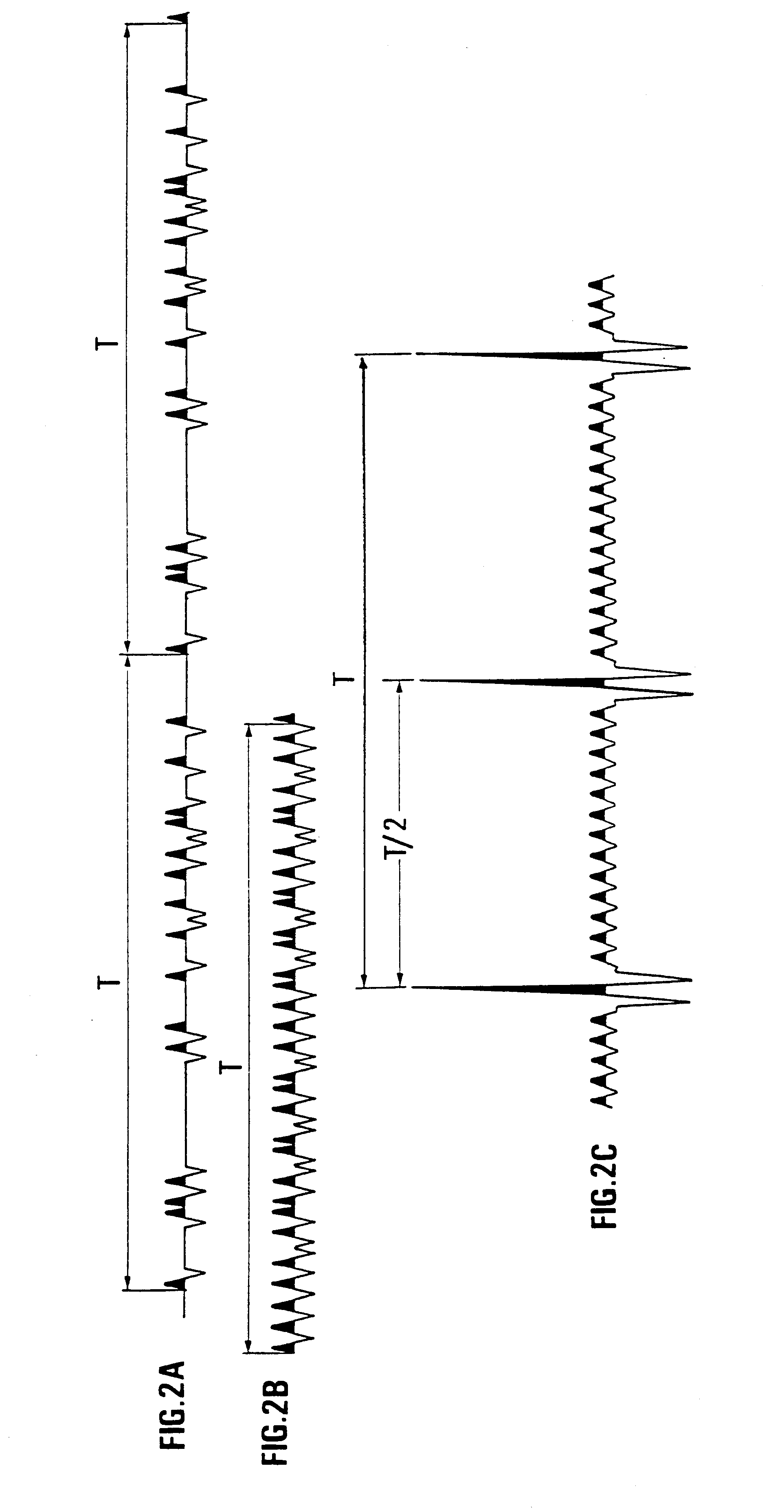
Seismic prospecting method and device using simultaneous emission of seismic signals obtained by coding a signal by pseudo-random sequences, and notably a periodic signal phase modulated by such sequences.Signals such as, for example, periodic signals phase modulated according to a pseudo-random code (binary for example), produced by a control unit, are for example emitted in the ground by means of vibrators, the seismic signals reflected by the subsoil discontinuities in response to the periodic signals emitted are picked up by receivers coupled with the formation and recorded in an acquisition and recording system. The periodic signals are emitted simultaneously by the vibrators. The control sequences of the coded periodic signals intended for all the vibrators are obtained either from the same random binary sequence with respective time lags evenly distributed over the length of the control sequence according to the number of vibrators used simultaneously (first mode), or from different sequences selected from among a group of sequences of minimum crosscorrelation (second mode), or by combining the two aforementioned modes. The respective contributions of the various vibrators are separated by correlating the signals received and recorded with signals constructed from the various control sequences obtained with time lags. The vibrators can be divided into several groups, the vibrators of each group being controlled by a binary sequence belonging to a minimum crosscorrelating group.Application: seismic prospecting or seismic monitoring of reservoirs for example.

Description

1. Field of the InventionThe present invention relates to a method and to a device used for land seismic prospecting by simultaneous emission in the ground of seismic signals emitted by several vibrators or groups of vibrators, these signals being obtained by coding a signal by pseudo-random sequences, and notably of a periodic signal phase modulated by such sequences.2. Description of the Prior ArtThere are well-known land seismic prospecting methods comprising transmission in the ground, for several seconds, of a periodic signal whose frequency varies continuously within a frequency band, reception by pickups of the signals reflected by underground reflectors and recording of the received signals. As a result of the emission time, the signals picked up are combinations of signals reflected by reflectors arranged at very different depths. The image of the various reflectors in the subsoil can only be recovered by processing the signals picked up, including correlation thereof with ...

Claims


Application Information

Patent Timeline
IPC IPC(8): G01V1/00
CPCG01V1/005
Inventor BECQUEY, MARC
Owner INST FR DU PETROLE
Learn More