Low-voltage transconductance amplifier/filters

a transconductance amplifier and filter technology, applied in the direction of low noise amplifiers, amplifier modifications to reduce non-linear distortion, frequency selective two-port networks, etc., can solve the problem of measurable degradation of the bit error rate (ber) in digital communication systems

Inactive Publication Date: 2004-03-09
SKYWORKS SOLUTIONS INC
View PDF9 Cites 73 Cited by
  • Summary
  • Abstract
  • Description
  • Claims
  • Application Information

AI Technical Summary

Problems solved by technology

The resulting interference causes measurable degradation...

Method used


Image

  • Low-voltage transconductance amplifier/filters
  • Low-voltage transconductance amplifier/filters
  • Low-voltage transconductance amplifier/filters

Examples


Embodiment Construction

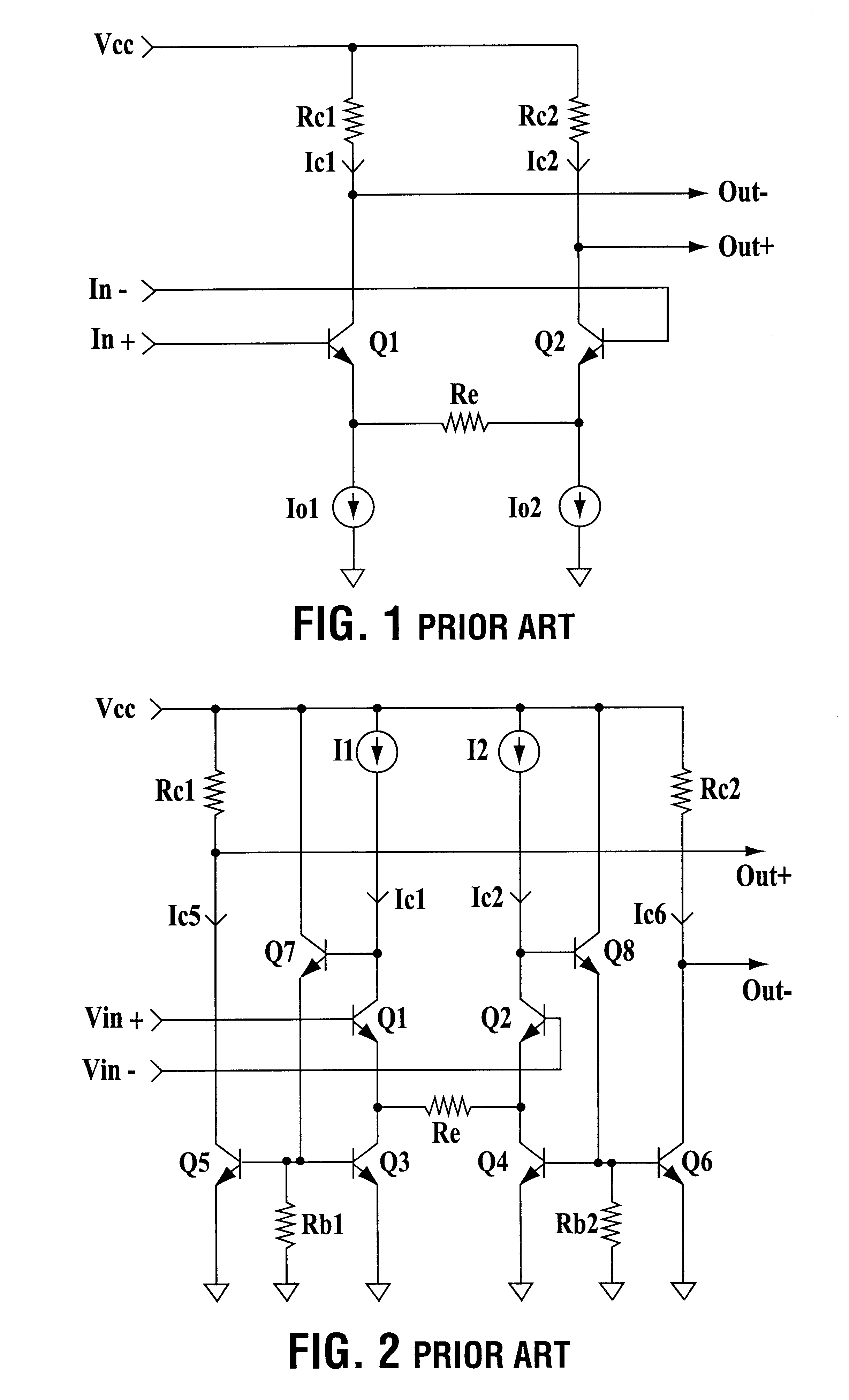
FIG. 1 presents a transconductance cell known in the art. The cell includes a transconductance core consists of two transistors Q1, Q2, that are coupled to differential inputs In+ and In-. A degeneration resistor Re couples the emitters of transistors Q1 and Q2 to the current sources Io1 and Io2. This degeneration resistor improves the third order intercept point IP3 of the cell. In the field of wireless communication devices, the incoming signals can be radio frequency (RF) or intermediate frequency (IF) signals. The incoming signal is present at the input ports, In+ and In- as a differential (balanced) voltage signal. The differential signal consists of a non-inverted and an inverted signal. The differential voltage signal is converted and amplified using the transistors Q1 and Q2 into two differential currents Ic1 and Ic2. The device that converts a voltage signal into a current signal and amplifies this signal before presenting an amplified voltage signal is called transconducta...


PUM


Abstract

Wireless communications devices must handle a wide range of useful signal levels and must also cope with large interfering signals of nearby frequencies. They often use transconductance amplifiers/filters as building blocks as such amplifier/filters exhibit good characteristics of both amplification and filtering. The transconductance cells described make use of feedbacks which involve no signal conversions. As the result, the cells have high linearity and yet can operate at low voltage.

Description

The invention resides in the field of wireless communication devices and systems where a wide variety of signals need to be handled. In particular it relates to transconductance cells for amplifying / filtering wireless signals, which cells have a high linearity over a wide range of signal levels and yet require a low operational voltage.BACKGROUND OF INVENTIONIn typical applications, a wireless receiver must operate over a wide range of signal levels as well as large interfering signals. The interfering signals emanate from users in adjacent channels, as well as from transmission sources which may be relatively far removed in frequency but have a large transmission power. When two interfering signals at frequencies f1 and f2 (where f1 and f2 are close to the desired signal frequency) are present, they will produce--due to amplifier nonlinearity--intermodulation products at frequencies 2f2-f1 and 2f1-f2. These can fall at frequencies close to the desired signal frequency. The resultin...

Claims


Application Information

Patent Timeline
IPC IPC(8): H03H11/04H03F1/32H03F3/45
CPCH03F1/3211H03F3/45098H03F3/45502H03H11/0422H03F2200/294H03F2200/372H03H2011/0494H03F3/45
Inventor BALTEANU, FLORINELCHERRY, JAMES
Owner SKYWORKS SOLUTIONS INC
Why Eureka
Try Eureka