Activation device for a piston/cylinder unit

a technology of activation device and piston, which is applied in the direction of vibration dampers, seating furniture, applications, etc., can solve the problems of inability to reliably prevent, reduce the problem of undesireable contact with the seat back, and undesirable operation behavior, and achieve the effect of increasing design freedom

a technology of activation device and piston, which is applied in the direction of vibration dampers, seating furniture, applications, etc., can solve the problems of inability to reliably prevent, reduce the problem of undesireable contact with the seat back, and undesirable operation behavior, and achieve the effect of increasing design freedom

US6705201B2Inactive Publication Date: 2004-03-16STABILUS

Image

  • Activation device for a piston/cylinder unit
  • Activation device for a piston/cylinder unit
  • Activation device for a piston/cylinder unit

Examples


Embodiment Construction

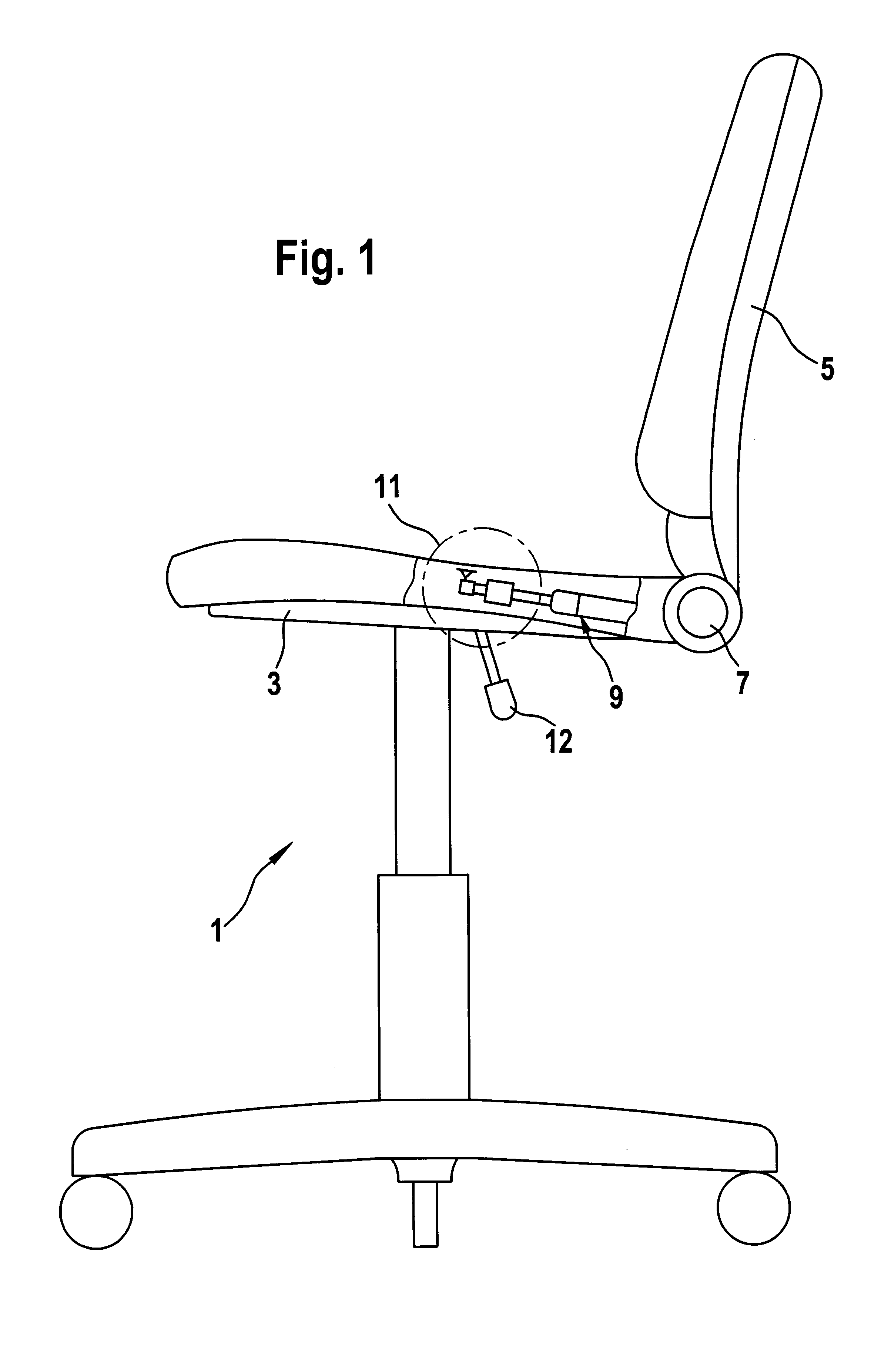
FIG. 1 shows a chair 1 having a seat carrier 3 and a seat back 5 supported on the sear carrier 3 so that the seat back 5 is pivotable about a bearing 7. A piston / cylinder unit 9 designed as a gas spring is functionally arranged between the seat back 5 and the seat carrier 3. By means of an activation device 11 including an actuating lever 12, the gas spring 9 may be switched into an inhibited movement position or an enabled movement position.

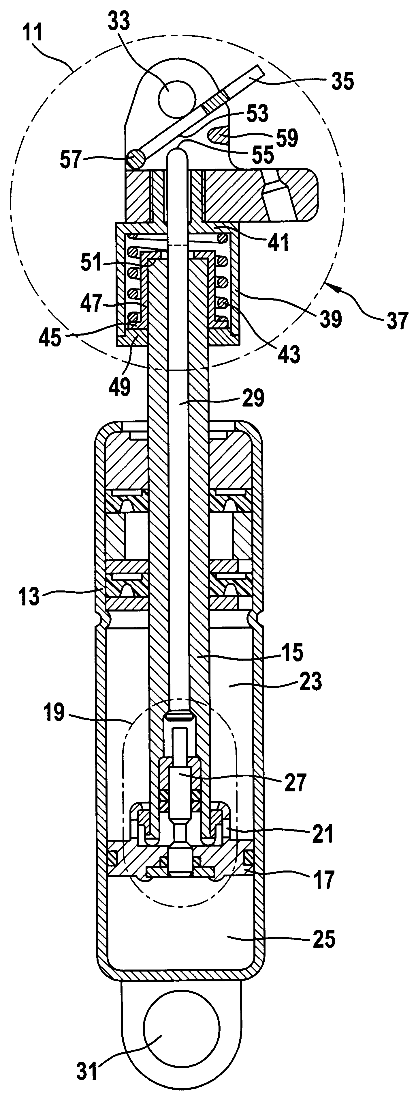
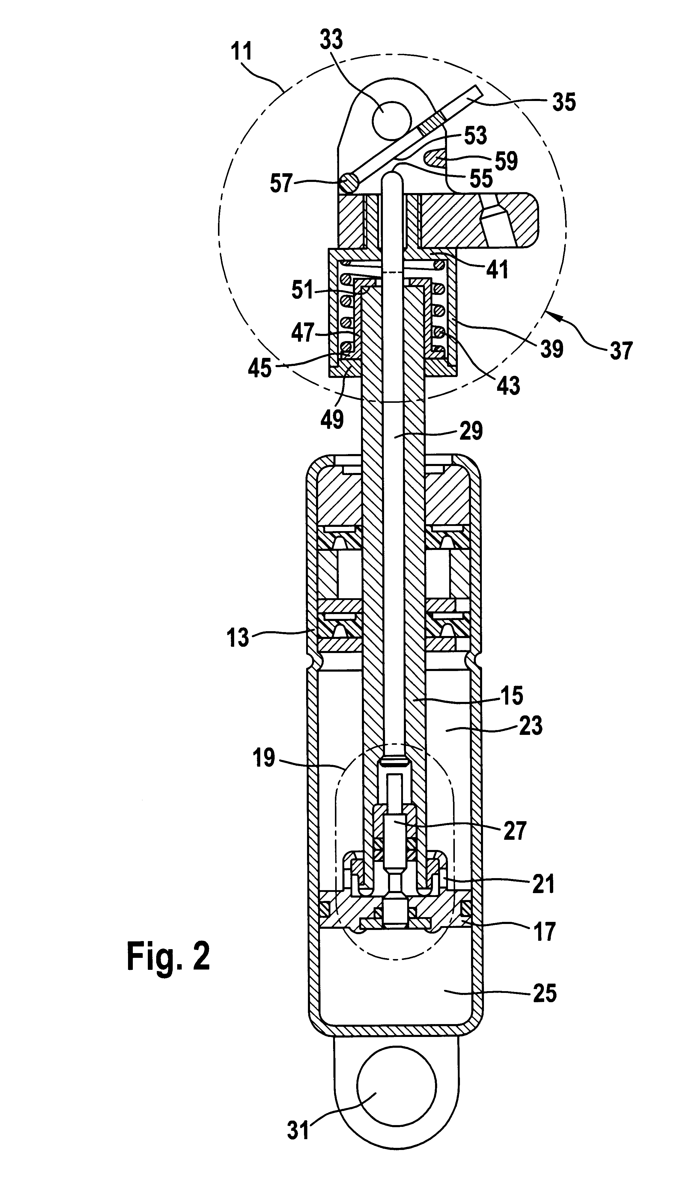
FIG. 2 shows, on an enlarged scale, the gas spring 9 with the activation device 11 as a sub-assembly. A piston rod 15 is arranged so that it can be moved axially within a cylinder 13 filled with a pressurized gas. A separating piston 17 which includes a valve device 19, is arranged at the end of the piston rod 15 located within the cylinder. The valve device 19 influences a flow connection 21 between working spaces 23, 25 of the cylinder which are separated by the piston. A valve push-rod 27 of the valve device 19 is actuatable by an activation ...


PUM


Abstract

A piston / cylinder unit, in particular a gas spring, includes a valve device for the operational motion of a piston rod. The valve device is activatable by an activation device, the activation device being connected near an actuation device and being connected to a load contact device, which influences the function of the valve device. The load contact device connects the actuation device to the valve device for the purpose of changing the adjustability of the valve device when the gas spring is loaded.

Description

BACKGROUND OF THE INVENTION1. Field of the InventionThe present invention relates to an activation device for a piston / cylinder unit, in particular for a gas spring, whose movement can be selectively inhibited and includes a valve device for operational motion of a piston rod and an activation device for operating the valve device.2. Description of the Prior ArtGas springs whose movement can be selectively inhibited are employed, for example, in chairs which have a seat back which is spring-supported and can be rigidly held by the selective inhibiting function of the gas spring. A chair user does not, however, continuously adopt the same posture on the chair. The seat back position can be very easily matched to the instantaneous seating position by the activation device. The user may also, for example, lean forward so that the seat back has no contact with the back of the user. If the activation device for the gas spring on the seat back is actuated while the user is in this positio...

Claims


Application Information

Patent Timeline
16 Mar 2004
Publication
US6705201B2
IPC
F16F9/02; F16F9/00
CPC
F16F9/0263
Inventors
KNOPP, AXEL; ENDERS, STEPHAN