Method for machining gear side face of bevel gear workpiece

A processing method and technology of bevel gears, which are applied to gear tooth manufacturing devices, gear tooth manufacturing tools, components with teeth, etc. Cutting, high production efficiency effect

Active Publication Date: 2019-05-03
KLINGELNBERG AG
View PDF6 Cites 0 Cited by
  • Summary
  • Abstract
  • Description
  • Claims
  • Application Information

AI Technical Summary

Problems solved by technology

The use of expensive and complex tooling systems is not always economically feasible

Method used


Image

  • Method for machining gear side face of bevel gear workpiece
  • Method for machining gear side face of bevel gear workpiece
  • Method for machining gear side face of bevel gear workpiece

Examples


Embodiment Construction

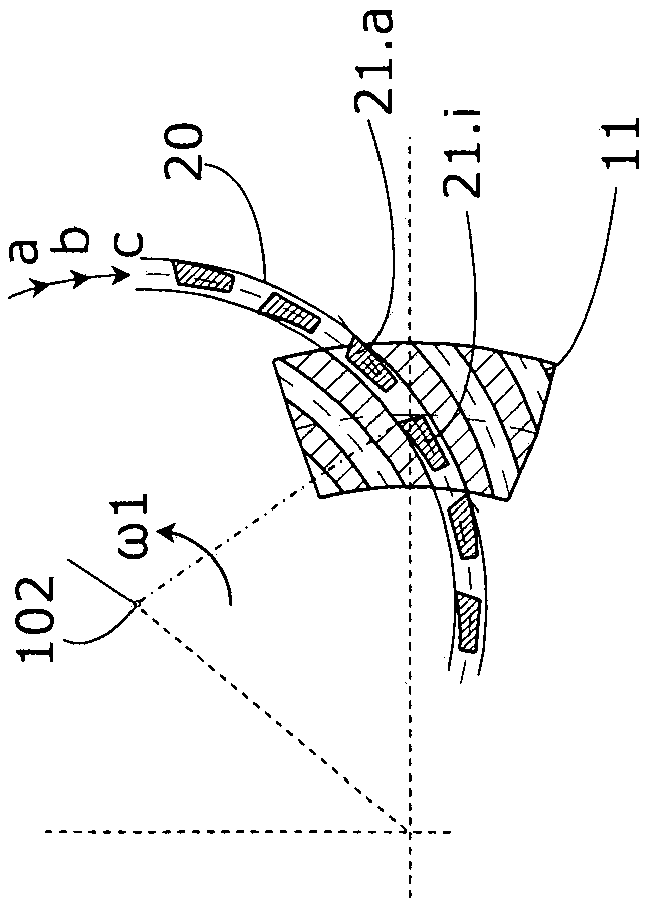
[0065] exist Figure 1A An exemplary basis for the single-index method (also known as intermittent index method, single-index method, or face milling) is shown in . Specifically, this is the single-division completion method.

[0066] The single-index half-finish method is used as the arc gear cutting method in the range of the first pass.

[0067] exist Figure 1A The single-division completion method is schematically shown in . In the present example, the common rolling motion of the bevel gear workpiece 11 and the cutterhead 20 , which occurs more slowly than the rotation ω1 of the cutterhead 20 , is not shown for the sake of simplicity. The picture shows a quasi-snapshot of the rolling process. The cutters 21.a, 21.i of the cutterhead 20 (for example the bar cutters of the bar cutterhead 20) perform a continuous movement in the form of a circular arc. The rotational movement of the cutter head 20 (here counterclockwise) is indicated by the arrow marked with ω1. To crea...


PUM


Abstract

A method for machining a bevel gear workpiece, comprising the steps that the bevel gear workpiece is fastened on a first workpiece main shaft of a first multi-axis machine tool; a first cutterhead comprising at least one internal cutting edge and at least one external cutting edge is fastened to a tool spindle of the multi-axis machine tool, and continuous rotation driving is carried out on the first cutterhead; a single-indexing machining method is adopted, and a rough cutting bevel gear workpiece is used, and the rough-cut bevel gear workpiece is removed from the first multi-axis machine tool, performing heat treatment on the rough cutting bevel gear workpiece; the rough cutting bevel gear workpiece is fastened on a workpiece main shaft of the second or the first multi-axis machine tool,and the second cutter disc is fastened to the first multi-axis machine tool or the second multi-axis machine tool, wherein the second cutterhead comprises an internal cutting edge and an external cutting edge which are arranged in a grouping mode; continuous rotation driving is carried out on the rough-cut bevel gear workpiece, and the coupling of the second cutterhead is driven continuously, anda continuous indexing machining method is adopted to finish machining of the concave tooth side surface and the convex tooth side surface of the bevel gear workpiece.

Description

technical field [0001] The subject of the invention is a method for machining bevel gear workpieces. Background technique [0002] Sometimes through the so-called Klingelnberg Methods Cut bevel gears (Cyclo-Palloid is a trademark of Klingelnberg GmbH, Germany). The Cyclo-Palloid method is a continuous indexing gear cutting method. [0003] In this method, for example, a two-piece cutterhead is used as the cutting tool. The two-piece cutterhead includes two nested cutterhead components, one of which supports a plurality of inner cutters and the other supports a plurality of outer cutters. Furthermore, each of said cutter head parts usually supports a so-called intermediate cutter. Internal cutters are used, for example, for soft machining of convex sides and external cutters for soft machining of concave sides of bevel gear workpieces. Such two-piece cutterheads require a gear cutting machine comprising corresponding transmissions for simultaneous rotational drive of th...

Claims


Application Information

Patent Timeline
Patent Type & Authority Applications(China)
IPC IPC(8): B23F9/08B23F23/00
CPCB23F21/12B23F21/236B23F23/00B23F23/12B23F9/08B23F9/086
Inventor J·韦伯K-M·里贝克
Owner KLINGELNBERG AG
Why Eureka
Try Eureka