Optical fiber splicing method and optical fiber

a technology of optical fiber and splicing method, which is applied in the direction of optical elements, manufacturing tools, instruments, etc., can solve the problems of insufficient splicing loss between splicing and splicing, inability to reduce splicing loss to a predetermined value, and difficulty in reducing splicing loss at room temperatur

Inactive Publication Date: 2004-03-16
SUMITOMO ELECTRIC IND LTD
View PDF5 Cites 6 Cited by
  • Summary
  • Abstract
  • Description
  • Claims
  • Application Information

AI Technical Summary

Benefits of technology

In the present invention, whether or not to terminate the alternation of heating and measuring steps is determined according to the splice loss value measured in the measuring step. If it is resultantly determined that the alternation should be terminated, then the alternation is terminated, whereby the optical fiber connecting operation is terminated. As a consequence, the splice loss at room temperature is fully reduced.
In the optical fiber splicing method in accordance with the present invention, a heating time in the first heating step may be made longer than that in the second and later heating steps. In this case, a desirable splice loss can be attained in a short time in total.

Problems solved by technology

In the case where the first and second optical fibers have respective mode-field diameters different from each other (e.g., one of them is a single-mode optical fiber whereas the other is a dispersion-compensating optical fiber) or in the case where the mode-field diameter of one of the first and second optical fibers is locally changed upon fusion, however, the splice loss therebetween is not sufficiently low.
However, the inventor has found that there is a case where the splice loss cannot be reduced to a predetermined value or less by the method disclosed in the above-mentioned publications.
Due to such a disparity, the splice loss at room temperature is hard to decrease sufficiently.

Method used


Image

  • Optical fiber splicing method and optical fiber
  • Optical fiber splicing method and optical fiber
  • Optical fiber splicing method and optical fiber

Examples


first embodiment

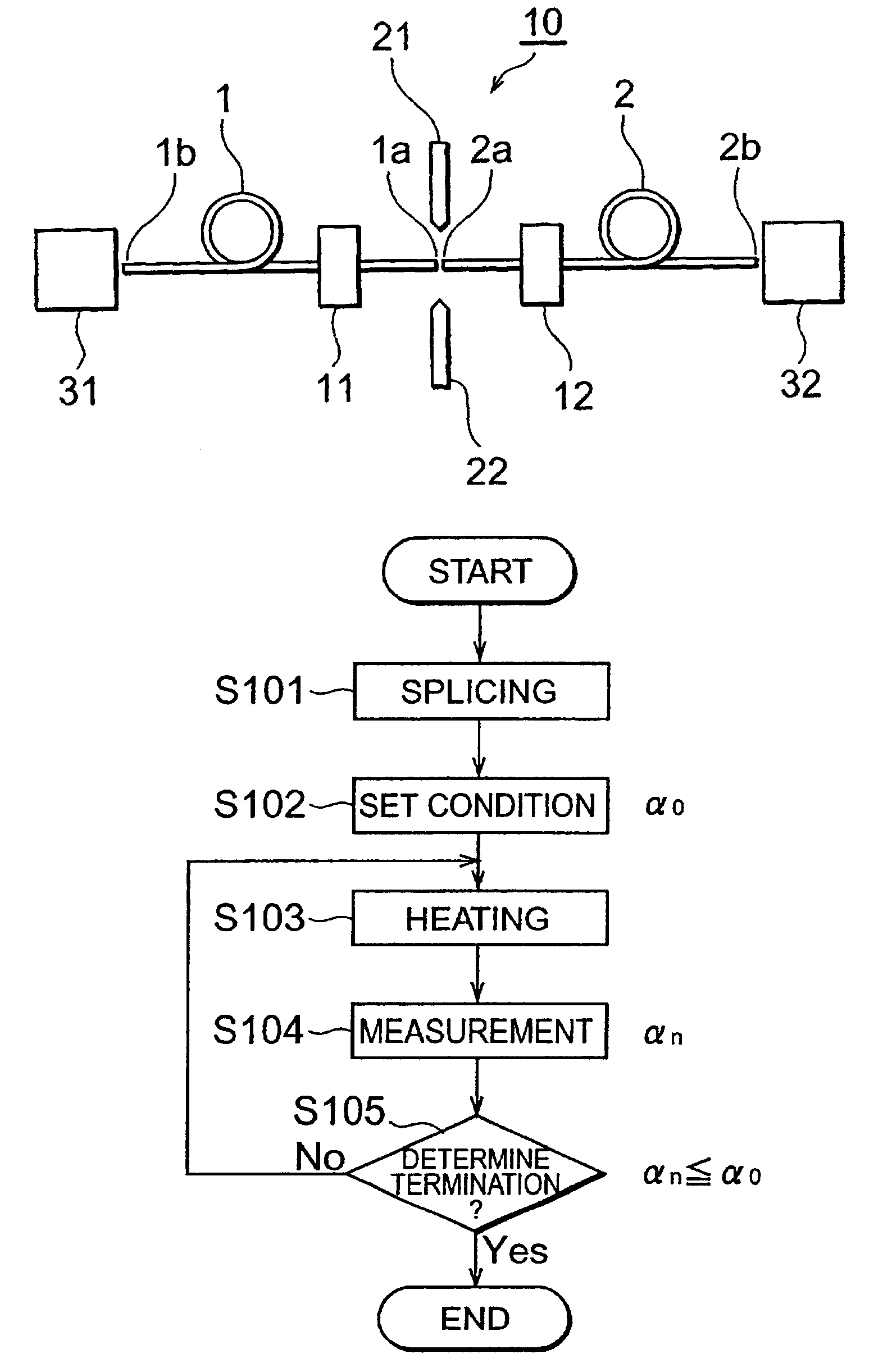
of the optical fiber splicing method in accordance with the first embodiment will now be explained. In this example, a single-mode optical fiber was used as the first optical fiber, whereas a dispersion-compensating optical fiber was used as the second optical fiber. Arc discharge was used in the splicing step, whereas the splice loss after the splicing step was 1.10 dB. A burner was used in the heating step, whereas a mixed gas composed of a propane gas (with a feed rate of 20 cc / min) and an oxygen gas (with a feed rate of 30 cc / min) was supplied to the burner. In each heating step, heating was carried out for 20 seconds. The time interval between one heating step and the next heating step was 10 seconds, during which the measuring step and termination determining step were carried out. The set value .alpha..sub.0 was 0.20 dB. The heating, measuring, and termination determining steps were repeatedly carried out until the measured splice loss .alpha..sub.n became the set value .alph...

second embodiment

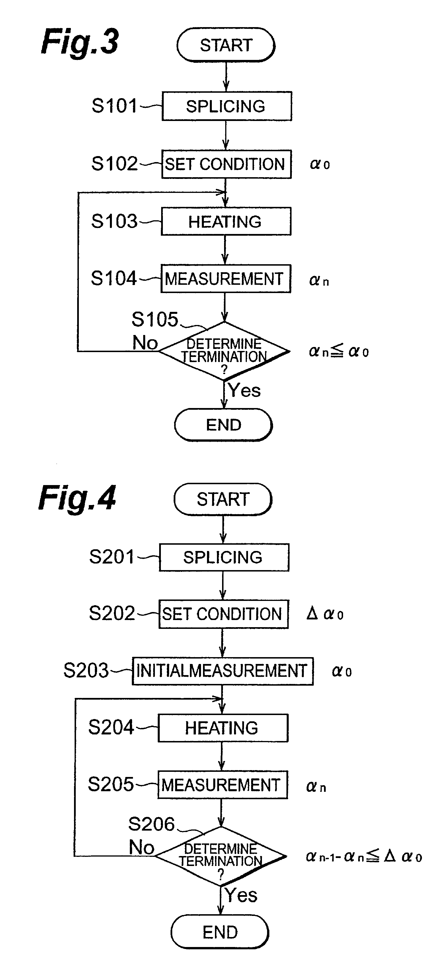
A second embodiment of the optical fiber splicing method in accordance with the present invention will now be explained with reference to FIG. 4. The optical fiber splicing method in accordance with the second embodiment includes a splicing step (S201), a condition setting step (S202), an initial measurement step (S203), a heating step (S204), a measuring step (S205), and a termination determining step (S206).

The splicing step (S201) is similar to S101 in the first embodiment. In its subsequent condition setting step (S202), a set value .DELTA..alpha..sub.0 used in the termination determining step (S206), which will be carried out later, is set. In the initial measurement step (S203), the splice loss .alpha..sub.0 between the first and second optical fibers fused in the splicing step (S201) is measured. Thereafter, the heating step (S204), measuring step (S205), and termination determining step (S206) are carried out repeatedly.

In the termination determining step (S206), the differe...

specific example 2-1

of the optical fiber splicing method in accordance with the second embodiment will now be explained. The optical fiber, arc discharge, burner, mixed gas, each heating time, and times of the measuring and termination determining steps used in this example are the same as those in Example 1. The set value .DELTA..alpha..sub.0 was 0.01 dB. Then, the heating, measuring, and termination determining steps were repeated until the measured difference .DELTA..alpha..sub.n became the set value .DELTA..alpha..sub.0 or less. As a result, the measured difference .DELTA..alpha..sub.n became the set value .DELTA..alpha..sub.0 or less at the time when the number n of alternation reached 33, whereby the optical fiber connecting operation was terminated. The time required after terminating the condition setting step was 980 seconds. The finally obtained splice loss .alpha..sub.33 was 0.19 dB.


PUM

PropertyMeasurementUnit
temperatureaaaaaaaaaa

Abstract

An optical fiber splicing method capable of fully reducing the splice loss at room temperature is provided. In the optical fiber splicing method in accordance with the present invention, respective end faces of optical fibers are fused together in a splicing step (S101). In a condition setting step (S102), a set value alpha0 is set. Thereafter, a heating step (S103), a measuring step (S104), and a termination determining step (S105) are carried out repeatedly. In the heating step, a region including the fusion-spliced point is heated under a predetermined heating condition. In the measuring step, splice loss is measured. In the termination determining step, the splice loss alphan measured in the measuring step and the set value alpha0 set in the condition setting step are compared with each other in terms of magnitude. If the splice loss alphan is not greater than the set value alpha0, then it is determined that the alternation should be terminated, whereby the optical fiber connecting operation is terminated.

Description

1. Field of the InventionThe present invention relates to an optical fiber splicing method in which respective end faces of first and second optical fibers are fused and spliced to each other, and an optical fiber made by this method.2. Related Background ArtKnown as methods of connecting first and second optical fibers to each other are connector connection and fusion splicing. The fusion splicing, in which respective end faces of the first and second optical fibers are fused and spliced to each other, yields a lower splice loss and higher reliability than the connector connection does. Therefore, the fusion splicing is employed more often in general. In the case where the first and second optical fibers have respective mode-field diameters different from each other (e.g., one of them is a single-mode optical fiber whereas the other is a dispersion-compensating optical fiber) or in the case where the mode-field diameter of one of the first and second optical fibers is locally chang...

Claims


Application Information

Patent Timeline
Patent Type & Authority Patents(United States)
IPC IPC(8): G02B6/255G01N21/67G01N21/72
CPCG01N21/67G01N21/72
Inventor NAKAMURA, MOTONORIKASUU, OSAMUYOKOTA, DAISUKEOHGA, YUICHI
Owner SUMITOMO ELECTRIC IND LTD
Why Eureka
Try Eureka