Resistant surface reflector

a surface reflector and reflective technology, applied in the direction of optics, instruments, mountings, etc., can solve the problems of loss of energy, surface is very sensitive to mechanical influence, and high purity of bright alloys with a high degree of aluminum based purity, and achieves high stability against wiping

Inactive Publication Date: 2004-03-23
CONSTELLIUM SWITZERLAND +1
View PDF34 Cites 34 Cited by
  • Summary
  • Abstract
  • Description
  • Claims
  • Application Information

AI Technical Summary

Benefits of technology

The purpose of the present invention is to avoid the disadvantages described and to propose reflectors in which the re...

Problems solved by technology

The known methods have the further disadvantage that expensive, high grade aluminum based bright alloys with a high degree of purity have to be ...

Method used


Image

  • Resistant surface reflector
  • Resistant surface reflector

Examples


Embodiment Construction

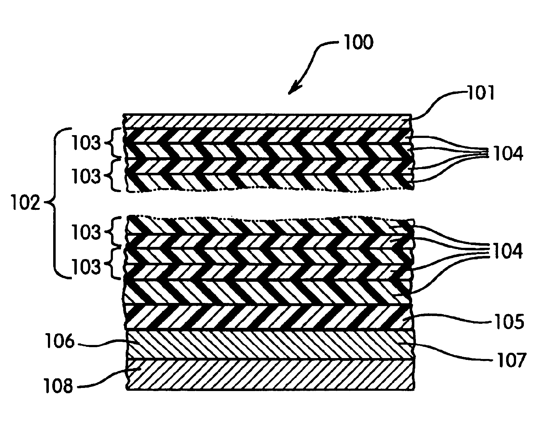
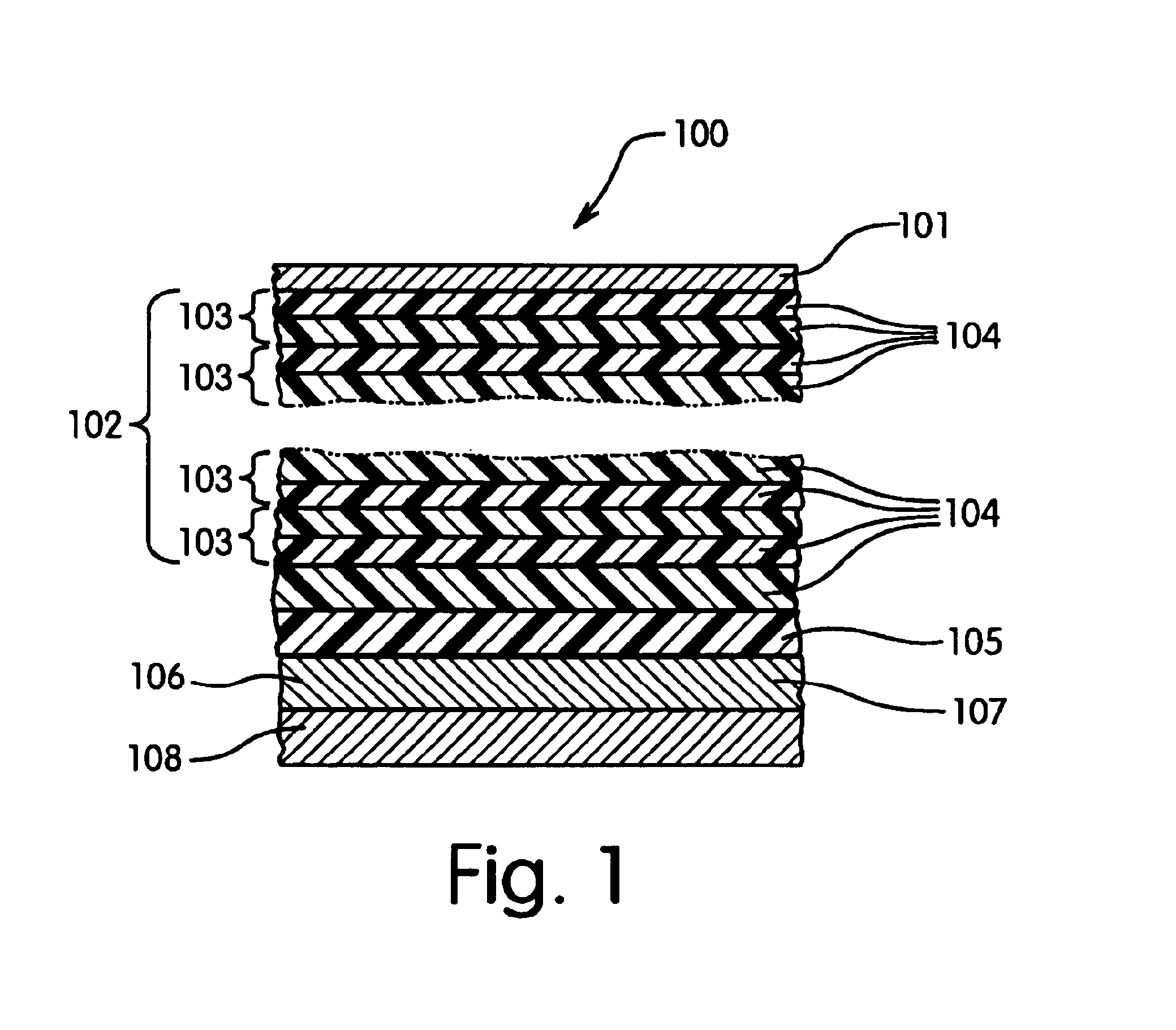
Various test samples of aluminum or aluminum alloys are partly pretreated by anodization and partly simply degreased and then coated with a lacquer. A sequence of reflective layers is deposited on the lacquer coat by means of a PVD process. The sequence of reflective layers consists successively of the aluminum reflecting layer in a thickness of 50 nm and deposited thereon firstly a silicon dioxide layer having an optical thickness of .lambda. / 4 followed by a titanium dioxide layer having an optical thickness of .lambda. / 4. In accordance with the invention, the protective layer is applied as the outermost layer by a further PVD process in the form of a layer of SiO.sub.2 having a thickness from 5 to 10 nm. In each of the control samples the protective layer is not present. All samples are subjected to the wiping test in accordance with DIN 58196 and the stability against wiping of the sample is assessed. The samples in accordance with the invention are graded after every 50 test cyc...


PUM


Abstract

A reflector with high total reflection which is resistant to mechanical stresses. The reflector includes a reflector body and superimposed thereon (a) a functional coating such as a varnish, (b) a reflecting layer structure composed of a reflecting metallic layer and optionally arranged thereon one or several transparent ceramic layers, for example, layers having an optical depth of lambda/2. The reflecting layer structure contains, as its surface layer, a protective layer. The protective layer is a silicon oxide of general formula SiOx, wherein x is a number from 1.1 to 2.0, or it is aluminum oxide of formula Al2O3, in a thickness of 3 nm or more. The protective layer protects the underlying layers from mechanical damages. In the DIN 58196 abrasion test the protected surface does not show any damages after 50 test cycles with 100 abrasion strokes.

Description

1. Field of the InventionThe present invention relates to a reflector which is resistant to mechanical attack and with high total reflectance, comprising a reflector body and arranged thereon:a) a functional coating; andb) a sequence of reflective layers containing one reflective layer and several transparent layers.The invention also relates to the use of such reflectors.2. BackgroundManufacture of strips of bright materials, e.g. highest grade aluminum or aluminum based AlMg alloys with purity percentage of 99.8% and higher, e.g., 99.9%, and rolled surfaces that produce diffuse or directed light reflection, depending on the application, are generally well-known. For the purpose of increasing directed reflection (degree of brilliance), chemical or electrolytic burnishing followed by anodic oxidation of the surface of strips of this kind, in order to produce a protective layer, e.g. 1.5 .mu.m thick, is also well-known.The known methods have the further disadvantage that expensive, h...

Claims


Application Information

Patent Timeline
IPC IPC(8): G02B5/08G02B1/10
CPCG02B1/105G02B5/08G02B5/0858G02B5/0866G02B1/111G02B1/14
Inventor GILLICH, VOLKMARKIRIN, RENATOFUCHS, ROMAN
Owner CONSTELLIUM SWITZERLAND
Why Eureka
Try Eureka