Level shifter and electro-optical apparatus incorporating the same

a level shifter and electro-optical technology, applied in the field of level shifters, can solve the problems of indeterminate on/off status of the first and second switching elements, waste of power, and indeterminate potential at the output terminal

Inactive Publication Date: 2004-03-30
TCL CHINA STAR OPTOELECTRONICS TECH CO LTD
View PDF5 Cites 18 Cited by
  • Summary
  • Abstract
  • Description
  • Claims
  • Application Information

AI Technical Summary

Benefits of technology

According to the above arrangement, once on / off status of the first and the second switching elements is determined, the potential at the output terminal is subsequently prevented from becoming indeterminate, due to voltage attenuation of the first or the second capacitor at the output terminal.
Accordingly, in this arrangement, preferably, the "power supply voltages" and the "reference voltages" supplied to the offset circuits are at least partially replaced with the "low-amplitude logic signal." According to this arrangement, for example, if the offset circuits are implemented by N-channel transistors and P-channel transistors as described above, the potential difference therebetween changes in synchronization with the low-amplitude logic signal. Thus, periods of reduced potential difference, compared with the arrangement in which the power supply voltages and the reference voltages are supplied, can be achieved. The reduction in the potential difference serves to reduce power consumption.
Although the low-amplitude logic signal is used to reduce the potential difference between the N-channel transistors and the P-channel transistors constituting the offset circuits in the above arrangement, the present invention is not limited thereto, and a signal synchronized with the low-amplitude logic signal may be used.
Since the first capacitor and the first offset circuit are absent as described above, the constituent devices are eliminated, serving to enhance manufacturing yield and to reduce cost.
By applying a level shifter according to the present invention to a driving circuit of an electro-optical apparatus, resolution and number of steps in intensity level can be considerably increased. Furthermore, scale of circuitry can be reduced.
As described hereinabove, according to the present invention, a level shifter that has a simple configuration and that allows fast operation can be implemented.

Problems solved by technology

However, a problem exists that when a logic signal having a low frequency is input, or when an input logic signal is maintained at the same logic level, on / off status of the first and the second switching elements becomes indeterminate.
However, in an initial state, for example, immediately after power-up, the potential at the output terminal inevitably becomes indeterminate unless the logic level of the input logic signal transits.
In particular, in the first and second offset circuit, a problem exists that generally a small current flows to cause a waste of power.
For example, if the first and second offset circuits are implemented by N-channel transistors and P-channel transistors as described above, a small current flows therebetween, causing a waste of power.
However, when the level shifter 100 is formed in an integrated form, it is difficult to achieve an ideal balance between the characteristics of the P-channel and N-channel TFTs, because of variations that occur in manufacturing, etc.
Thus, a problem exists that the output is indeterminate in an initial state, for example, immediately after power-up.

Method used


Image

  • Level shifter and electro-optical apparatus incorporating the same
  • Level shifter and electro-optical apparatus incorporating the same
  • Level shifter and electro-optical apparatus incorporating the same

Examples


Embodiment Construction

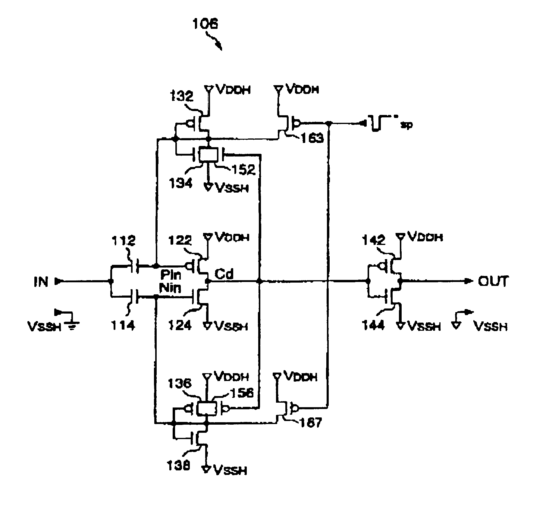
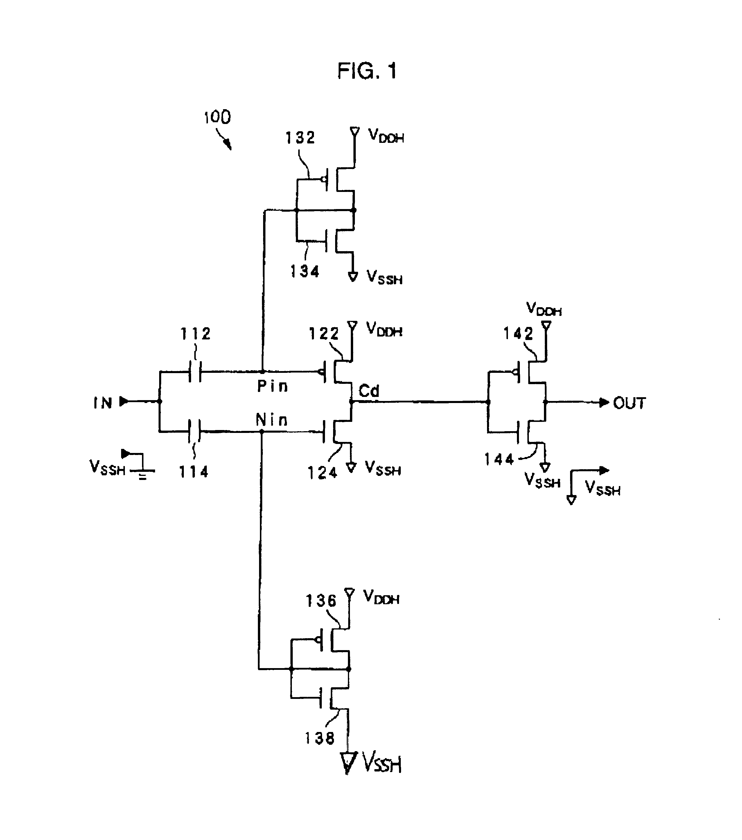
Although the fourth and fifth embodiments employ configurations based on the level shifter 100 according to the first embodiment, the present invention is not limited thereto. That is, short-circuiting of the source of the TFT 134 or 138 constituting the first or the second offset circuit with the input terminal IN (the fourth embodiment) and the absence of the first or the second offset circuit (the fifth embodiment), etc. may be applied to FIG. 5 (the second embodiment), FIG. 7 (the first mode of the third embodiment), and FIG. 9 (the second mode of the third embodiment).

Furthermore, it is to be understood that an arrangement having a combination of the features of the fourth and fifth embodiments is within the scope of the present invention. FIG. 15 shows, as an example thereof, a level shifter 200, in which the source of the TFT 138 in the second offset circuit is short-circuited with the input terminal IN via the short-circuiting line 401 as in the fourth embodiment and in whic...


PUM

PropertyMeasurementUnit
voltageaaaaaaaaaa
voltageaaaaaaaaaa
voltageaaaaaaaaaa

Abstract

The invention simplifies the configuration of a level shifter and to allow fast operation. A level shifter includes a capacitor, to a first end of which a low-amplitude logic signal is input; first TFTs to apply an offset voltage to a second end of the capacitor; a capacitor, to a first end of which the low-amplitude logic signal is input; third TFTs to apply an offset voltage to a second end of the capacitor; and second TFTs connected in series between a supply line of a power supply voltage for a high-amplitude logic signal and a supply line of a reference voltage therefor, a node therebetween serving as an output terminal. A threshold voltage of one of the second TFTs is set to be not higher than the offset voltage applied by the first TFTs , and an offset voltage of the other of the second TFTs is set to be higher than or equal to the offset voltage applied by the third TFTs.

Description

1. Field of InventionThe present invention relates to a level shifter that has a simple configuration and that quickly converts a low-amplitude logic signal into a high-amplitude logic signal. The present invention also relates to an electro-optical apparatus incorporating the level shifter.2. Description of Related ArtIn recent years, electro-optical apparatuses that allow display by electro-optical change in electro-optical materials, such as liquid crystal and organic EL (electroluminescence) materials, have become widely used in various information processing apparatuses and television sets as alternative display devices to cathode-ray tube (CRT) displays.Such electro-optical apparatuses can be broadly classified, by their driving methods, into active matrix type apparatuses, in which pixels are driven by non-linear devices, such as transistors and diodes, and passive matrix type apparatuses, in which pixels are driven without using non-linear devices. It is believed that electr...

Claims


Application Information

Patent Timeline
Patent Type & Authority Patents(United States)
IPC IPC(8): H03K19/0185H03K19/017H03K19/01G09G3/36G02F1/1345G02F1/133G02F1/1368G09G3/20
CPCH03K19/01707H03K19/018571G09G3/3688G09G2310/0289G09G3/36
Inventor FUJIKAWA, SHINSUKEOZAWA, TOKURO
Owner TCL CHINA STAR OPTOELECTRONICS TECH CO LTD
Why Eureka
Try Eureka