
Tool Magazine

a tool magazine and tool technology, applied in the field of multi-tool holding and automatically indexing tool magazines, can solve the problems of large amount of inertia to be overcome, tool magazines to occupy more space in relation, and complicated control systems of tool magazines

Inactive Publication Date: 2004-04-06
SANKYO SEISAKUSHO
View PDF29 Cites 32 Cited by
  • Summary
  • Abstract
  • Description
  • Claims
  • Application Information

AI Technical Summary

Benefits of technology

The invention is a multiple tool holding automatically indexing tool magazine for a metal processing machine. The main technical effects of the invention are that it can accommodate a larger number of tools in a relatively small space and quickly transport tools to the tool removal station with a minimum inertial effect. The tool magazine is structured so as to allow for more efficient space utilization at the site where the metal processing machine is used. The invention proposes an improved design that reduces the size of the tool magazine and allows for more tools to be held in a smaller space. The tool magazine is designed to simultaneously index the main and sub-tables to the desired rotational angle and achieve a smooth rotational action of the main and sub-tables that suppresses vibrations generated by the moving tool magazine and reduces abrasional wear. The position of each stored tool can be known in real time, thus allowing for an accurate positioning operation the next time that the tool is needed. Additional tool pots may be installed to further increase the tool holding capacity of the tool magazine.

Problems solved by technology

Because the tool holding pots are arranged in a circular pattern, the size of the entire magazine increases as the number of tools it is designed to hold increases, thus causing the tool magazine to occupy more space in relation to the number of tools held therein.
There is a problem, however, in that the number of tool pots that can be installed to the aforesaid oval track structure is limited by the length of that structure, thus necessitating the use of multiple tool magazines in cases where it is desired to use more tools than a single magazine can accommodate, and further necessitating the need for a relatively large space to accommodate these multiple tool magazines.
Moreover, the tool magazine control system becomes more complicated when multiple tool magazines are used.
As a result, there is a large amount of inertia to be overcome as the drive system must move all of the tools when a tool indexing operation is executed.
This large amount of inertia results in the generation of excessive shock when the tool magazine starts and stops, thus making it difficult to precisely control the start-stop indexing action of the tool magazine at high speeds.

Method used


Image

  • Tool Magazine
  • Tool Magazine
  • Tool Magazine

Examples


first embodiment

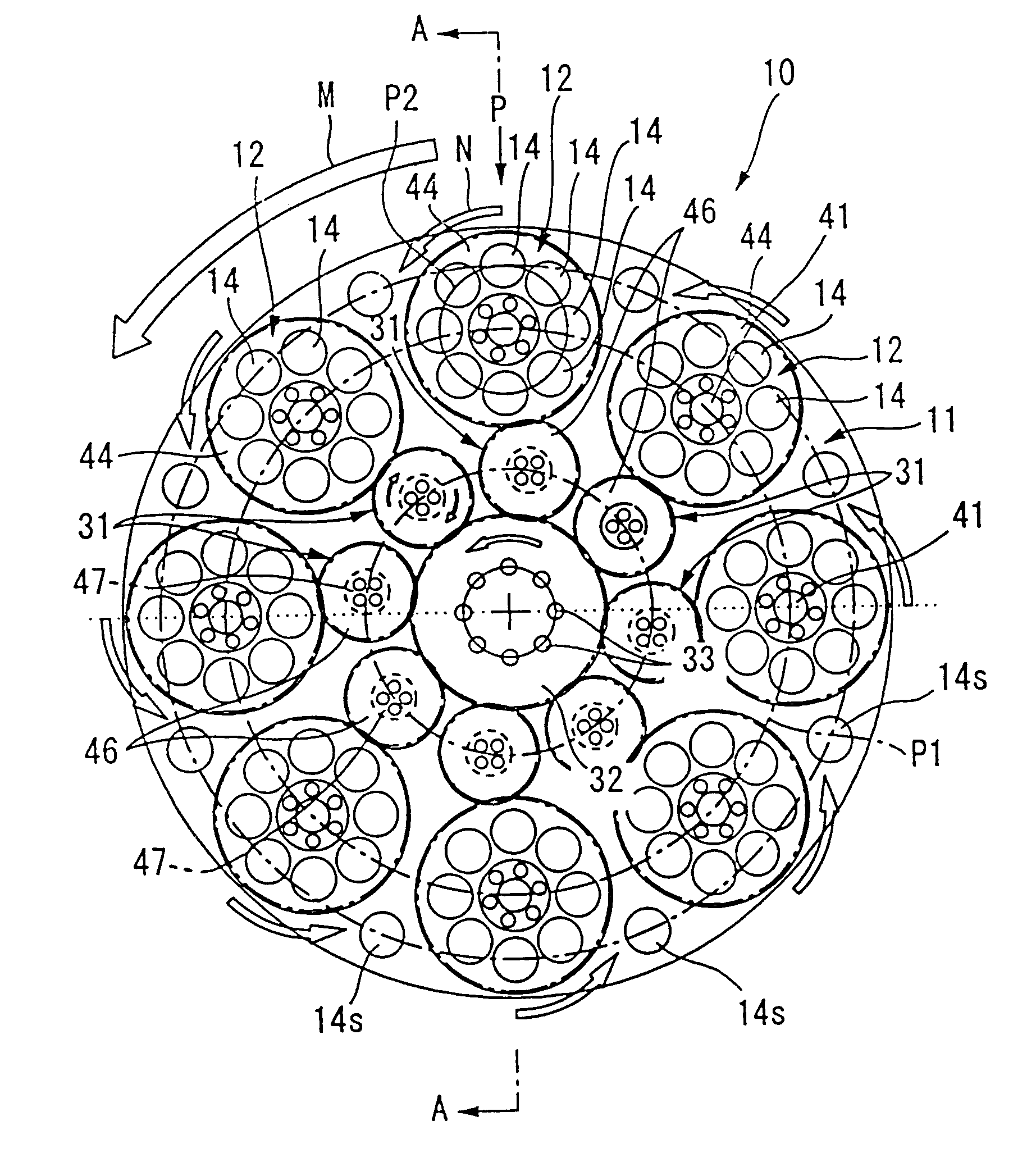
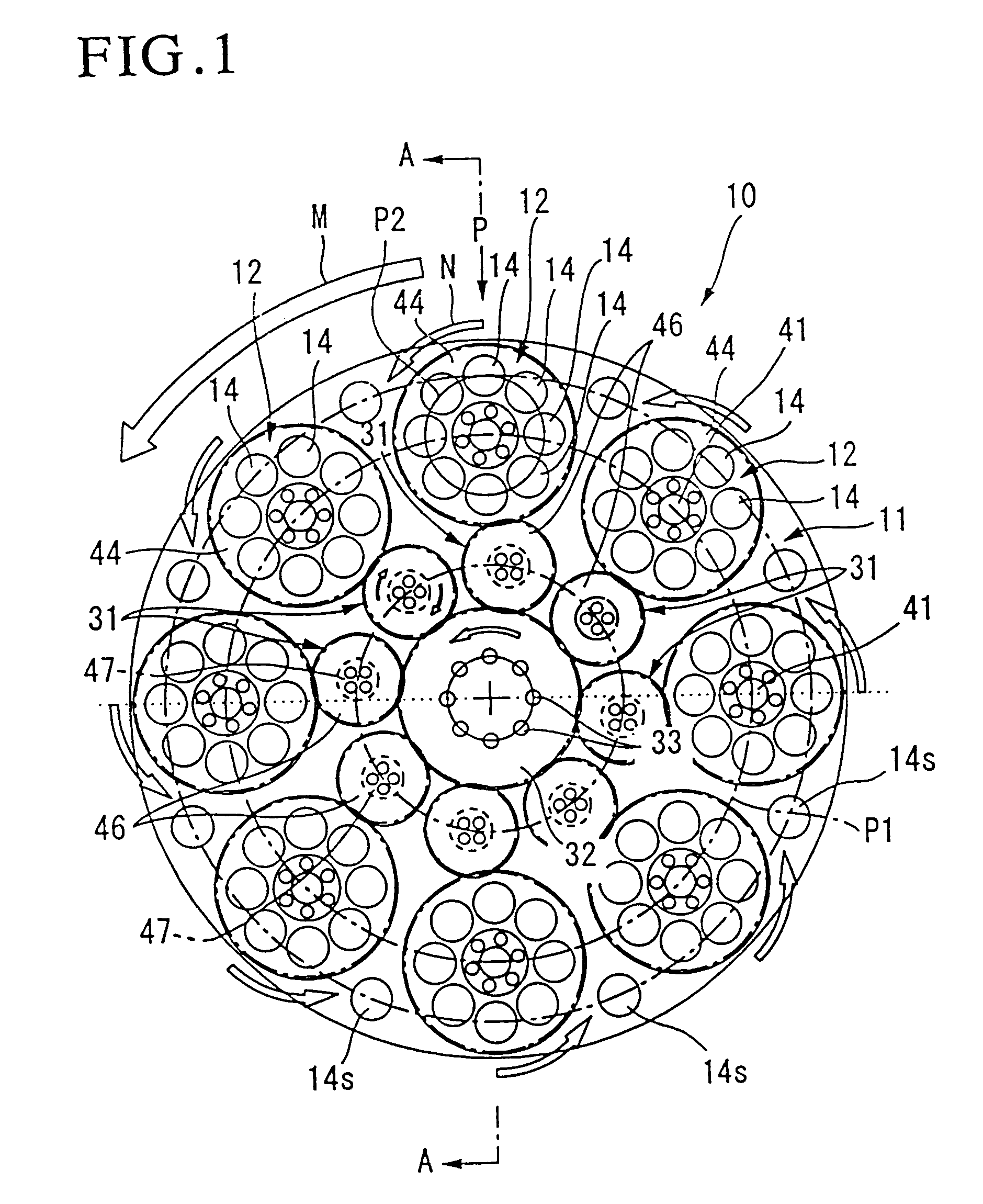
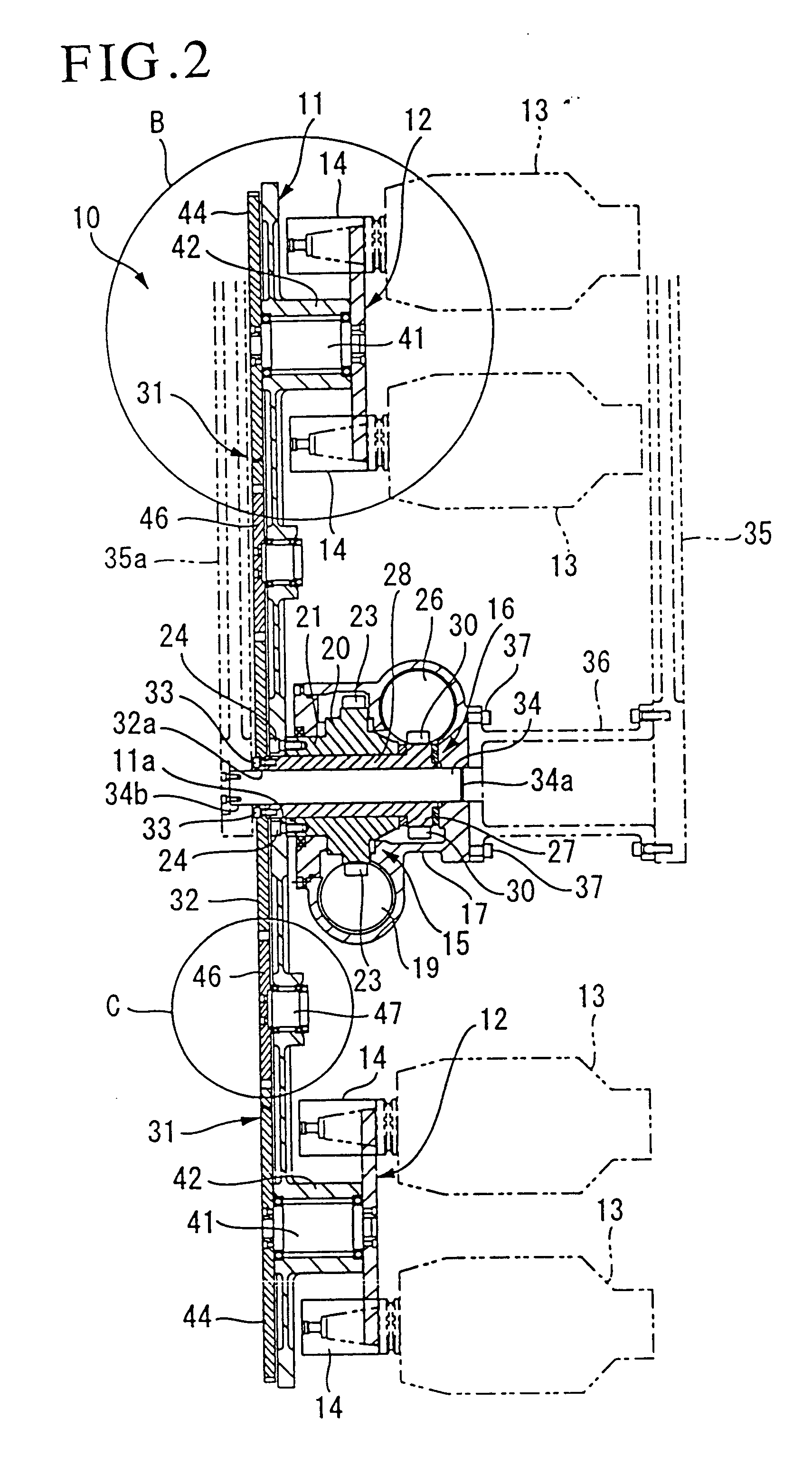
FIGS. 1 through 7 present the invention. Tool magazine 10 is a round table-type structure, and as FIGS. 1 and 2 demonstrate, is comprised of disc-shaped main table 11 to which multiple disc-shaped sub-tables 12 are installed in a radial pattern at uniform intervals on a radial arc shown as P1. In this embodiment, a total of eight sub-tables are mounted to main table 11. Tool pots 14 are installed to each sub-table on radial arc P2 as means of storing various machining tools on the tool magazine. In this embodiment each sub-table is capable of holding up to eight tools. The main table and sub-tables can be rotated to the desired angular phase, through the use of an indexing mechanism, as means of bringing the tool pot holding the designated tool 13 to the tool removal station "P" where the tool is removed from the tool pot for use by the metal processing machine. As FIG. 1 demonstrates, a large number of tools can be stored in this type of tool magazine. Main indexing mechanism 15 is...

second embodiment

This second embodiment provides for a structure in which radial indexing device 53 is connected to rotatable sub-shaft 41 of sub-table 12a as a way to accurately establish the stop positions of the sub-table, thus providing means of precisely indexing the sub-table at the tool exchange position. In addition, angular nub 28a and corresponding recess part 52a provide for a releasable joint that, when connected, is capable of precisely positioning the sub-table at the tool exchange position.

FIG. 19 demonstrates a third embodiment of the invention in which tool magazine 10b is similar to the first and second embodiments in regard to the following structures. Multiple sub-tables 12b, on which tool pots 14 are installed, are arranged in a radial pattern on main table 11, sub-tables 12b being angularly rotatable to a desired position as means of providing a tool indexing movement that is able to bring a designated tool 13 (residing in tool pot 14) to tool removal station "P" for removal. T...


PUM

PropertyMeasurementUnit
rotational torqueaaaaaaaaaa
radiusaaaaaaaaaa
diameteraaaaaaaaaa

Abstract

A automatically indexing tool magazine, of the type attached to machining centers that incorporate an automatic tool change function, able to hold a relatively large number of tools in a compact space as means of improving space efficiency. The tool magazine is comprised of a rotatable main table and multiple sub-tables rotatably attached to the main table in a uniformly spaced radial pattern, each sub-table being equipped with a number of tool pots likewise arranged in a uniformly spaced radial pattern. The tool pots serve as containers into which machining tools can be inserted or removed. The main table and sub-tables are rotatably indexed by means of respective main table and sub-table indexing mechanisms. The tool pot holding the tool designated for removal is transported to a tool removal position through the rotational indexing movement of the main table and appropriate sub-table.

Description

1. Field of the InventionThe invention relates to a multiple tool holding automatically indexing tool magazine used by a metal processing machine of the type that incorporates an automatic tool change function, specifically, a tool magazine that can be used to store a greater number of tools in a smaller space than conventional tool magazines.2. Description of the Related ArtJapanese Unexamined Patent Application No. 2000-94252 teaches a tool magazine that performs the same automatic tool indexing function as the invention. The tool magazine put forth in the aforesaid patent is comprised of multiple tool holding pots radially arranged on the outer surface of a round table-like structure. Because the tool holding pots are arranged in a circular pattern, the size of the entire magazine increases as the number of tools it is designed to hold increases, thus causing the tool magazine to occupy more space in relation to the number of tools held therein.The following structure has been us...

Claims


Application Information

Patent Timeline
Patent Type & Authority Patents(United States)
IPC IPC(8): B23Q1/25B23Q1/54B23Q3/155B23Q3/157
CPCB23Q1/5468B23Q3/15526Y10T483/1809Y10T483/1795Y10T483/1882Y10T483/1873Y10T483/18Y10T483/1738Y10T483/1845Y10T74/14Y10T483/175B23Q16/10B23Q3/15539B23Q3/15722B23Q2003/15532Y10T83/8732B23Q3/157
Inventor KATO, HEIZABURO
Owner SANKYO SEISAKUSHO
Learn More