
Venous valve and graft combination

a venous valve and graft technology, applied in the field of venous valve and graft combination, can solve the problems of blood pooling in the body extremities, complicated surgical techniques for valve replacement, and limitations of existing pharmaceutical and surgical treatments for such venous disorders

Inactive Publication Date: 2004-04-06
WILDER JOHN G +1
View PDF13 Cites 167 Cited by
  • Summary
  • Abstract
  • Description
  • Claims
  • Application Information

AI Technical Summary

Benefits of technology

The solution effectively prevents reflux, maintains blood flow at low pressure differentials, reduces thrombosis risk, and allows for flexible sizing and delivery methods, enhancing patient ambulatory functions without causing vein irritation.

Problems solved by technology

Much of vascular research and development to date has centered on the arterial system, as problems in this system tend to be life threatening.
When, due to disease, injury, or congenital defect, valves do not properly operate, reflux can occur, causing blood to pool in the body extremities.
Existing forms of pharmaceutical and surgical treatments for such venous disorders all have limitations.
Surgical techniques for valve replacement are complicated and delicate.
No currently available prosthetic valve fully addresses the special needs of the venous environment.
All such devices place radially outward forces on the inner vein wall, causing radial stiffening.
With a large percentage change in diameter during pulsation, any foreign object exerting radial stiffness causes local irritation to the vein wall.
Calcified and otherwise stiffened valves do not function well at low pressure differentials.

Method used


Image

  • Venous valve and graft combination
  • Venous valve and graft combination
  • Venous valve and graft combination

Examples


Embodiment Construction

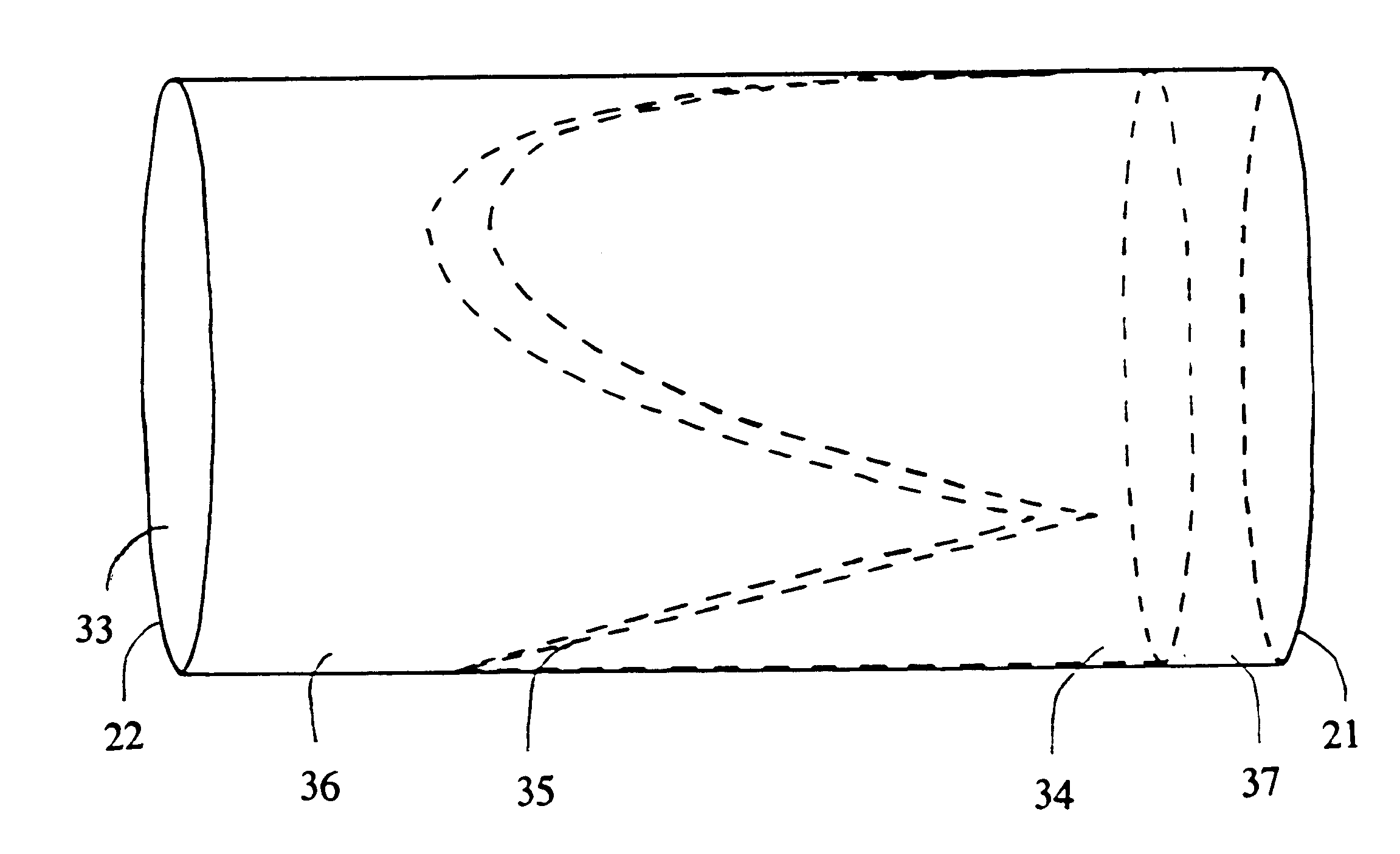
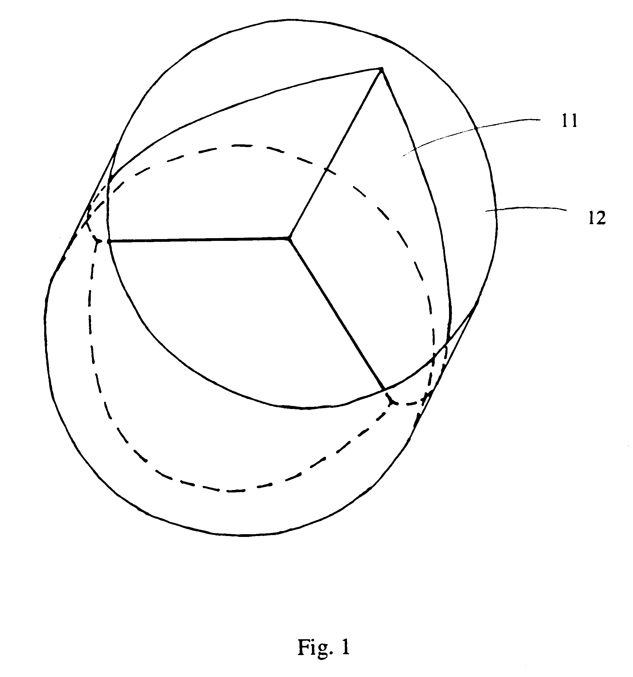
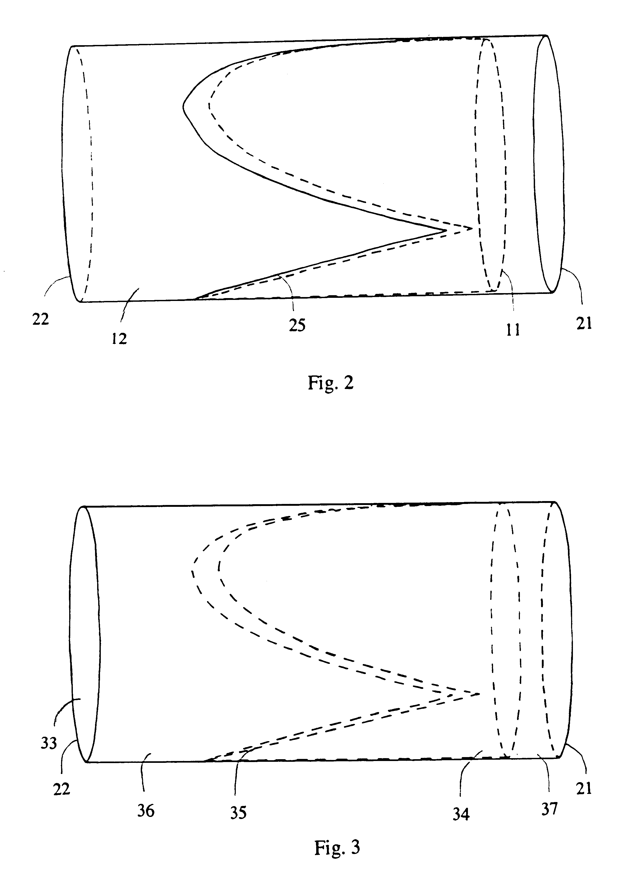
A preferred embodiment of the valve and graft combination of the present invention is illustrated by FIGS. 1 and 2. The closed valve and graft combination shown in FIG. 1 demonstrates that the valve dimensions are related to the graft diameter. The streamlined profile when valve 11 is fully open (shown in FIG. 2) is a particularly desirable design feature. When the valve is fully open, the diameter for blood flow is essentially the graft 12 diameter minus two thicknesses of the valve material. The diameter of the graft is adjusted accordingly for the patient's vein (typically less than 10 mm). As the graft is held firmly against the inner vein wall by the venous blood pressure, the diameter available for blood flow becomes the original vein lumen minus four thicknesses of material. The lengths of the graft from the warp insertion line 25 (shown in FIG. 2) to the proximal end 21 and to the distal end 22 can also be adjusted to the patient's requirements. A taper can further be develo...


PUM


Abstract

A synthetic venous valve and graft combination that exerts no radial force at the valve site is disclosed. The trilobed valve (11) is passively actuated by venous blood pressure changes. When open, the aperture for blood flow is approximately that of the original vein. The prosthesis is useful for replacing nonfunctioning venous valves in the human vasculature.

Description

Not applicable.BACKGROUND--FIELD OF INVENTIONOur invention is a synthetic venous valve and graft combination, useful to replace a diseased, injured, or otherwise nonfunctioning venous valve in the human vasculature.BACKGROUND--DISCUSSION OF PRIOR ARTSignificant differences between the venous environment and the arterial environment should be considered when designing prosthetic venous valves. Much of vascular research and development to date has centered on the arterial system, as problems in this system tend to be life threatening. The most obvious difference between the two environments is the lower oxygen content of the venous blood. The lower oxygen content is a key factor in the exceedingly high propensity towards thrombus formation. Blood in the arterial system is moved rapidly and at high pressure by the heart. In contrast, blood is moved through the veins at slightly over half the arterial pressure (close to the measured systolic pressure) and more slowly. Blood flow rates i...

Claims


Application Information

Patent Timeline
Patent Type & Authority Patents(United States)
IPC IPC(8): A61F2/24
CPCA61F2/2412A61F2/2475
Inventor WILDER, JOHN G.TESAR, ALETA
Owner WILDER JOHN G
Learn More