Data path for high performance pattern generator

a high-performance, data-path technology, applied in the direction of photomechanical equipment, instruments, manufacturing tools, etc., can solve the problems that the raster scanning pattern generator is approaching the end of its economic life, and achieve the effects of reducing the limit on throughpu

Inactive Publication Date: 2004-04-06
MICRONIC LASER SYST AB
View PDF4 Cites 74 Cited by
  • Summary
  • Abstract
  • Description
  • Claims
  • Application Information

AI Technical Summary

Benefits of technology

It is therefore an object of the present invention to provide a method and an apparatus to alleviate the above-discussed problems with the prior art.

Problems solved by technology

However, being in principle serial devices, the raster scanning pattern generators are approaching their end of economic life.

Method used


Image

  • Data path for high performance pattern generator
  • Data path for high performance pattern generator
  • Data path for high performance pattern generator

Examples


Embodiment Construction

Embodiments of the invention will in the following be described by way of examples. However, it should be appreciated by those versed in the art that the invention is not limited to these examples.

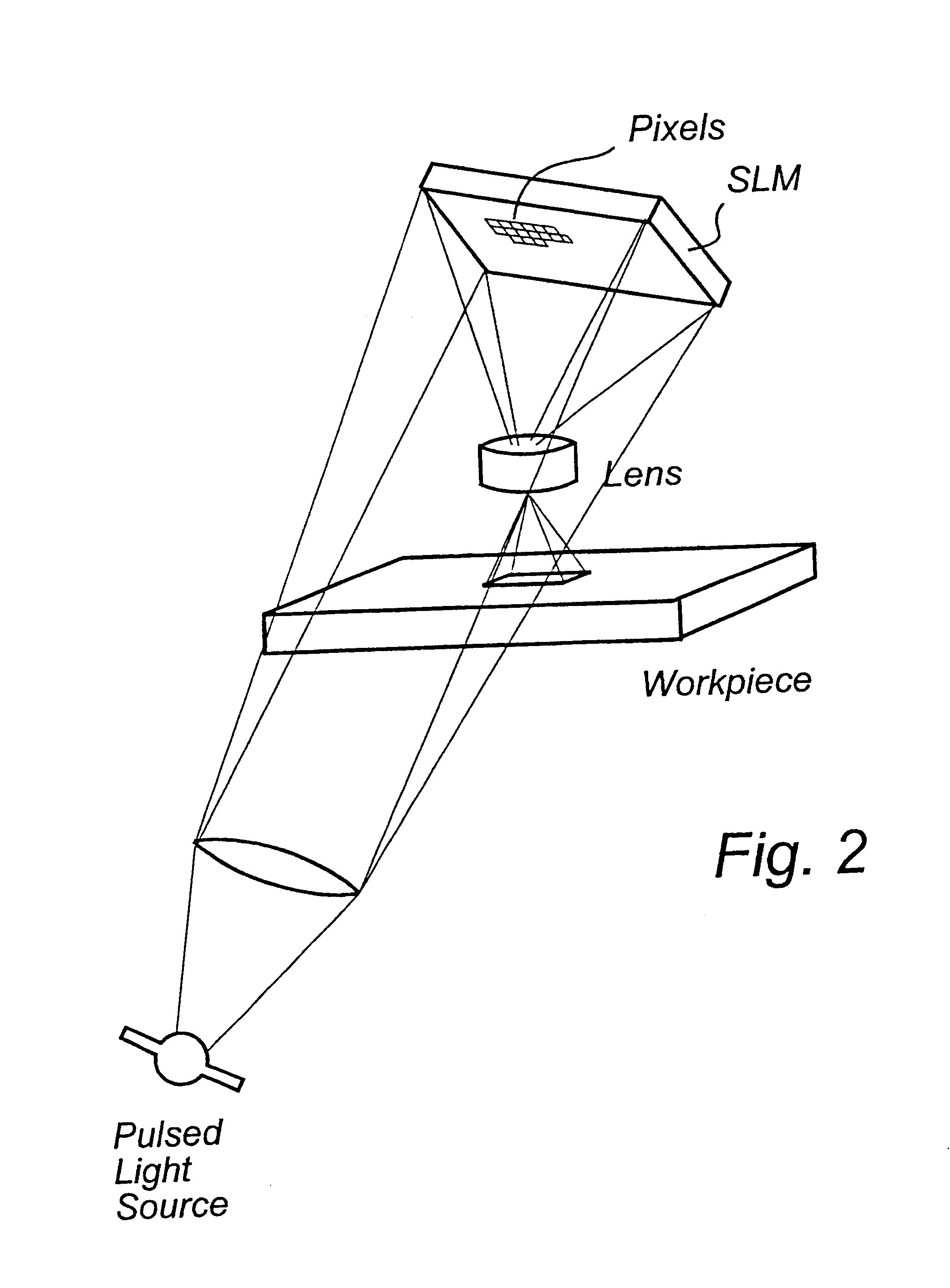
A preferred embodiment of the invention is a rasterizer for a high-end pattern generator (PG) for writing photomasks for the 0.13 .mu.m "design node". The PG is capable of writing features down to 180 nm. The pattern generator is described in PCT patent application SE99 / 00310 as using an analog reflective micromechanical SLM and projecting the image of the SLM through a demagnifying lens onto the mask blank, as is illustrated schematically in FIG. 2. The SLM has an array size 2048.times.512 pixels and each pixel is 16.times.16 .mu.m wide. The lens has the demagnification 160X and the projected size of an SLM pixel is 0.1.times.0.1 .mu.m. The analog pixels of the SLM are driven by a voltage with more than 50 levels, and preferably 65 levels, between full and zero exposure, corresponding to ...


PUM

PropertyMeasurementUnit
speedaaaaaaaaaa
lengthaaaaaaaaaa
voltageaaaaaaaaaa

Abstract

A high-speed datapath for a high-performance pattern generator such as an analog SLM for generating the image is disclosed. The data path has provisions for completely independent parallel data flows giving true scalability to arbitrarily high throughput. In a preferred embodiment areas on the SLM are assigned to specific rasterizing and fracturing processors. There is an overlap between fields for blending of the edges in the pattern and for computation of interaction between features in the pattern. The datapath has data integrity checks and a recovery mode when an error condition is raised, allowing it to recover from most errors without creating new errors.

Description

The present invention relates to high-end pattern generation, such as for the patterning of photomasks, microelectronic and microoptical devices and for production of display devices. Other applications of highly precise patterns such as security printing and interconnection devices are also related to the invention.The term pattern generator is used in the description to mean a machine that creates a physical pattern from data, typically by the action of light on a photosensitive surface.Patterning of photomasks for the production of integrated circuits is developing according to the so-called More's law, where every three years a new circuit generation with four times the complexity of the previous one is created. Thirty-five years ago the patterns were manually cut with knife in a red plastic film, so called Rubylith film. Later, the need for increasingly precise and complex patterns led to the development of the optical pattern generator with a computer-controlled stage and flas...

Claims


Application Information

Patent Timeline
Patent Type & Authority Patents(United States)
IPC IPC(8): G03F7/20G03F1/08H01L21/027
CPCG03F7/70291G03F7/704G03F7/70508Y10S707/99942Y10S707/99937G03F7/70358G03F7/70158
Inventor SANDSTROM, TORBJORNTHUREN, ANDERS
Owner MICRONIC LASER SYST AB
Why Eureka
Try Eureka