
Sequential numbering machine for injection moulds

a numbering machine and numbering technology, applied in the field of numbering machines for injection moulds, to avoid thereby possible jamming and malfunction

Inactive Publication Date: 2004-04-20
COMML DE UTILES Y MOLDES
View PDF10 Cites 13 Cited by
  • Summary
  • Abstract
  • Description
  • Claims
  • Application Information

AI Technical Summary

Benefits of technology

"The present invention proposes a sequential numbering machine for injection molding that is designed to resolve the problem of inefficient and unreliable numbering of plastic pieces. The machine is based on the arrangement and operation of cams and wheels, with the cams and wheels being enclosed in a cylindrical casing. The machine uses electromechanical impulses to actuate the spindle, which is pushed outward by a spring. The spindle has a toothed heel that engages with a lever, which is pressed against the cams and wheels. The lever is pressed against a positional lock to keep the cams and wheels immobilized during the turning of the cam. The machine also has a spring-guided plunger that can be used to mark plastic pieces. The machine is designed to be efficient, reliable, and adaptable to various applications."

Problems solved by technology

Nevertheless, although numerous types and forms of numbering machine exist for the marking of different pieces, objects and articles, no numbering machine is known in the plastic injection sector, which is simply due to the difficulty involved basically in achieving a level of total sealing, so that the plastic is not introduced in the injection process through the multiple moving pieces and spaces existing in the numbering machines marketed at the moment.

Method used


Image

  • Sequential numbering machine for injection moulds
  • Sequential numbering machine for injection moulds
  • Sequential numbering machine for injection moulds

Examples


Embodiment Construction

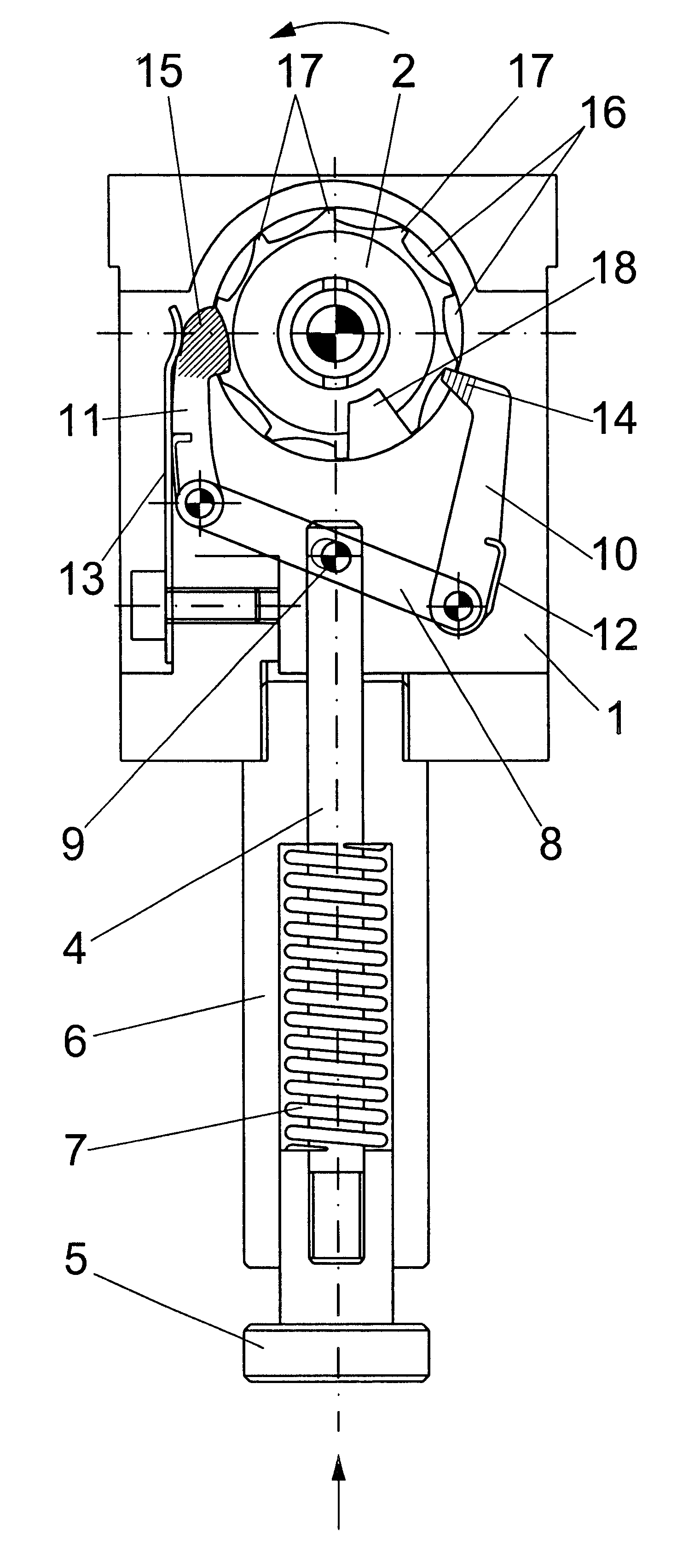
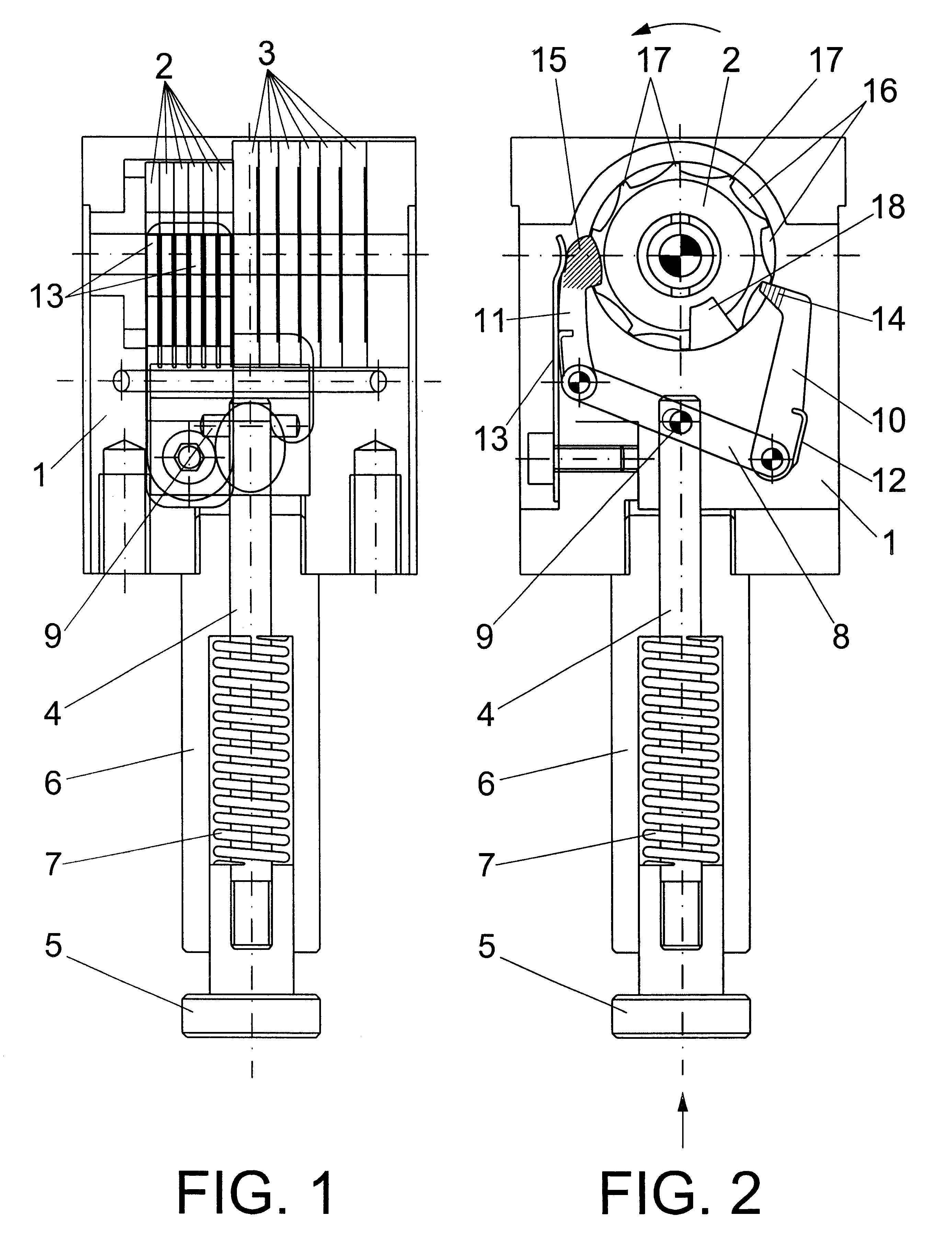
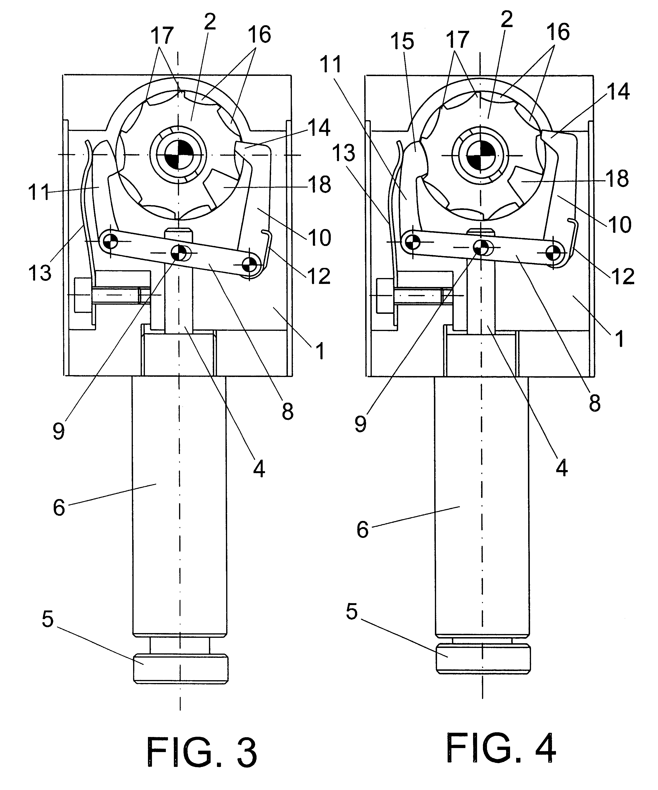
The numbering machine proposed, is foreseen precisely to resolve the problem explained above, being based on the adequate arrangement and operation of the cams and wheels which combine to form the numbering machine, all this enclosed in a cylindrical casing from which emerges a spindle finished in a plunger which is operated by electromechanical impulses, which spindle being associated with a spring which tends to constantly push it outward in order that the electromechanical impulse presses toward the interior and acts on a transversal lever mounted so that it can rotate about the spindle's end, which end being housed inside the cylindrical casing like the lever, which has on each of its ends an arm mounted also so that it can rotate but pushed constantly, in one case toward the cams of the numbering machine and in the other case toward the wheels of the numbering machine itself.

The cams and the wheels are connected in pairs, so that the sectorial turning of a cam signifies the tur...


PUM

PropertyMeasurementUnit
pressureaaaaaaaaaa
areaaaaaaaaaaa
mechanicalaaaaaaaaaa

Abstract

The numbering machine comprises a series of cams (2) and a series of wheels (3), each cam (2) being connected with a wheel (3), so that the turning of a cam (2) signifies the turning of a wheel (3). The cams (2) have on their periphery nine projections (17) and a recess or hollow (18), while each wheel (3) has on its periphery the digits corresponding to the first nine numbers. The assembly is mounted in an interior casing (1) from which a spindle (4) emerges operable sequentially in each process of injection of a piece, so that through that spindle (4) and by means of a lever (8) articulated thereto individual arms (10) and (11) are operated, the first of them having a toothed sector (14) the teeth of which are pushed for each tooth to press on a single cam (2) until the complete turn takes place, the interlocking taking place of a second tooth with the second cam (2) and so forth, so that in each sectorial turning of the cam (2) the sectorial turning of the respective wheel takes place (3) and therefore the sequential advance of the corresponding number. The arm (11) has a series of prongs (15) which maintain the wheels (3) immobilised with the exception of that which is operated by the corresponding cam (2). The numbering machine is foreseen for marking pieces obtained by injection.

Description

OBJECT OF THE INVENTIONThe present invention relates to a sequential numbering machine for injection moulds, the evident purpose of which is that of marking pieces which are obtained by injection moulding, so that the numbering machine acts in accordance with each electromechanical impulse which it receives in each injection cycle, or what is the same thing, in each injection moulded piece.It is an object of the invention to provide the plastics injection sector with a sequential numbering machine in order to be able to mark the pieces which are being obtained by injection, the operation being carried out automatically without the numbering machine being subjected to filtrations of plastic during the injection process, avoiding thereby possible jamming and malfunctioning.Numerous types of numbering machines are known for carrying out marking of different kinds, from marking with letters, to numbers, signs, logotypes, etc., so that the change from numbers or symbols is carried out ma...

Claims


Application Information

Patent Timeline
Patent Type & Authority Patents(United States)
IPC IPC(8): B29C45/37
CPCB29C45/374
Inventor NAVARRA PRUNA, ALBERTO
Owner COMML DE UTILES Y MOLDES
Learn More