Measurement while drilling electromagnetic telemetry system using a fixed downhole receiver

a technology of electromagnetic telemetry and downhole receiver, which is applied in the field of electromagnetic telemetry, can solve the problems of inability to achieve the effect of em telemetry, too high attenuation of em wave, and general limited em telemetry,

Inactive Publication Date: 2004-04-27
SCHLUMBERGER TECH CORP
View PDF18 Cites 147 Cited by
  • Summary
  • Abstract
  • Description
  • Claims
  • Application Information

AI Technical Summary

Problems solved by technology

Currently, EM telemetry is generally limited to shallow land rigs where the formations are quite resistive (i.e., on the order of ten ohm-m or more).
Under the current EM telemetry scheme, however, the attenuation of the EM wave is too high for this approach to be practical.
Moreover, the receiver being located on the drilling surface is typically subjected to high ambient EM noise from the drilling rig itself, thus further complicating the matter.
Even in such cases, however, the received EM signal might be quite small because of a likely low resistivity in those rock formations near the seabed.
Neither of these proposed techniques addresses the issue that the original EM signal received is small.
Because it is important to receive the drilling and geological data accurately and expeditiously at the surface to take immediate corrective action for any problems that may occur during the downhole operations, an EM telemetry scheme which relies upon receivers near or above the seabed will not suffice for accomplishing such while drilling in deeper formations.

Method used


Image

  • Measurement while drilling electromagnetic telemetry system using a fixed downhole receiver
  • Measurement while drilling electromagnetic telemetry system using a fixed downhole receiver
  • Measurement while drilling electromagnetic telemetry system using a fixed downhole receiver

Examples


Embodiment Construction

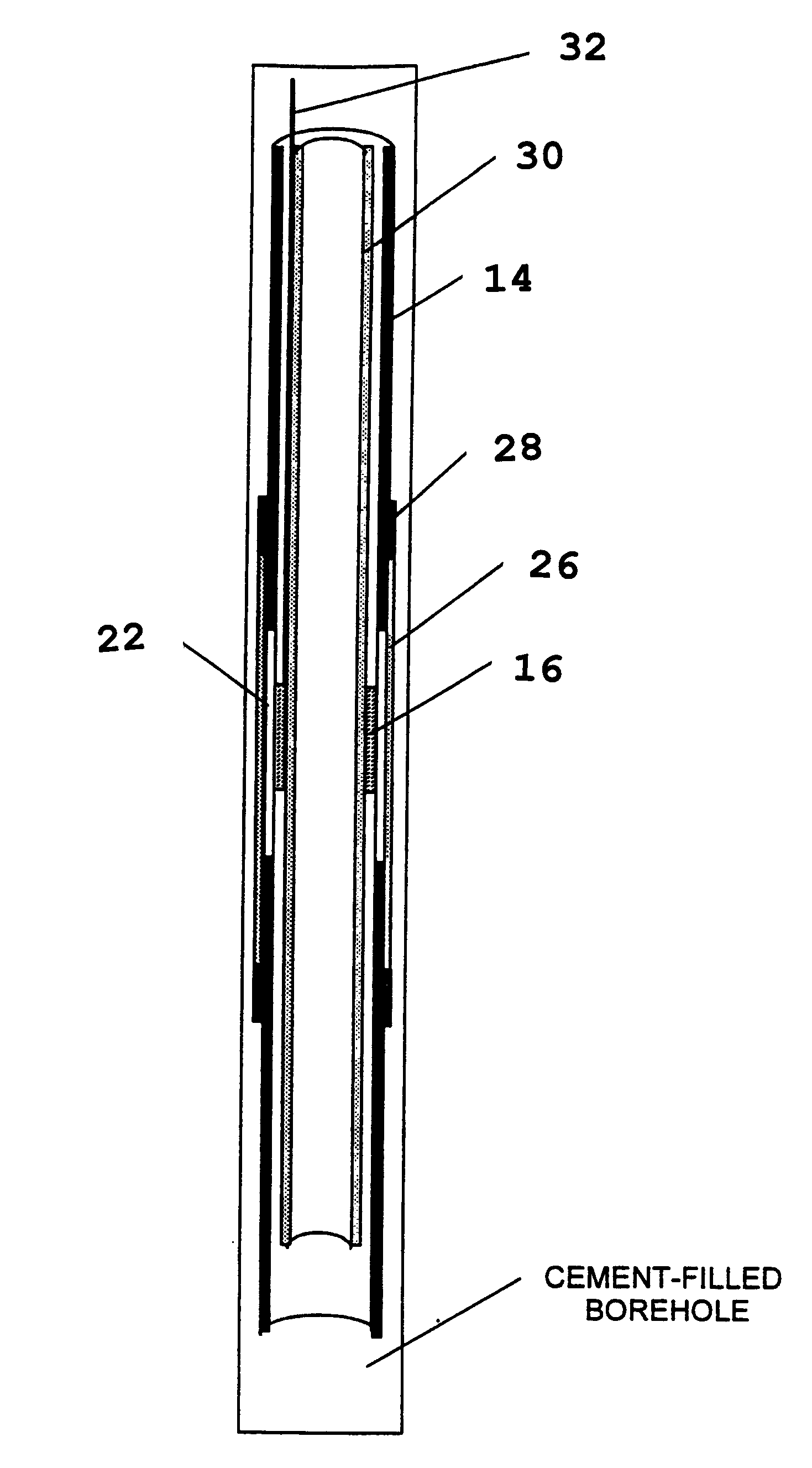
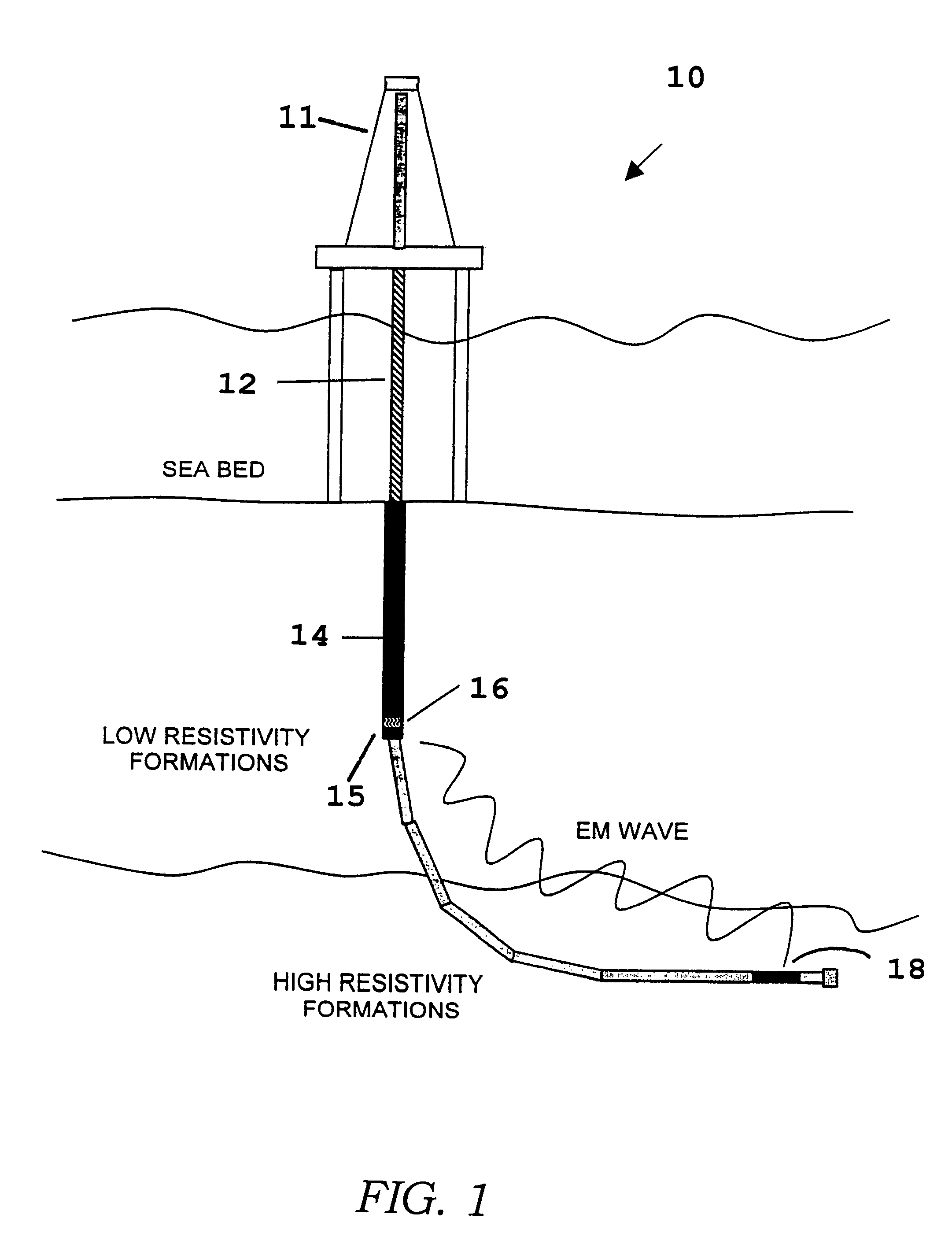
FIG. 1 shows an EM telemetry system 10 in accordance with one embodiment of the invention. The system 10 includes a drilling rig 11 and a riser 12, which extend from the earth's surface. According to one embodiment, the drilling rig 11 is deployed off shore and extends from a sea bed. The drilling rig 11 creates a borehole into the earth and a metallic outer casing 14, commonly known as a "tubular," is disposed within the borehole and cemented therein.

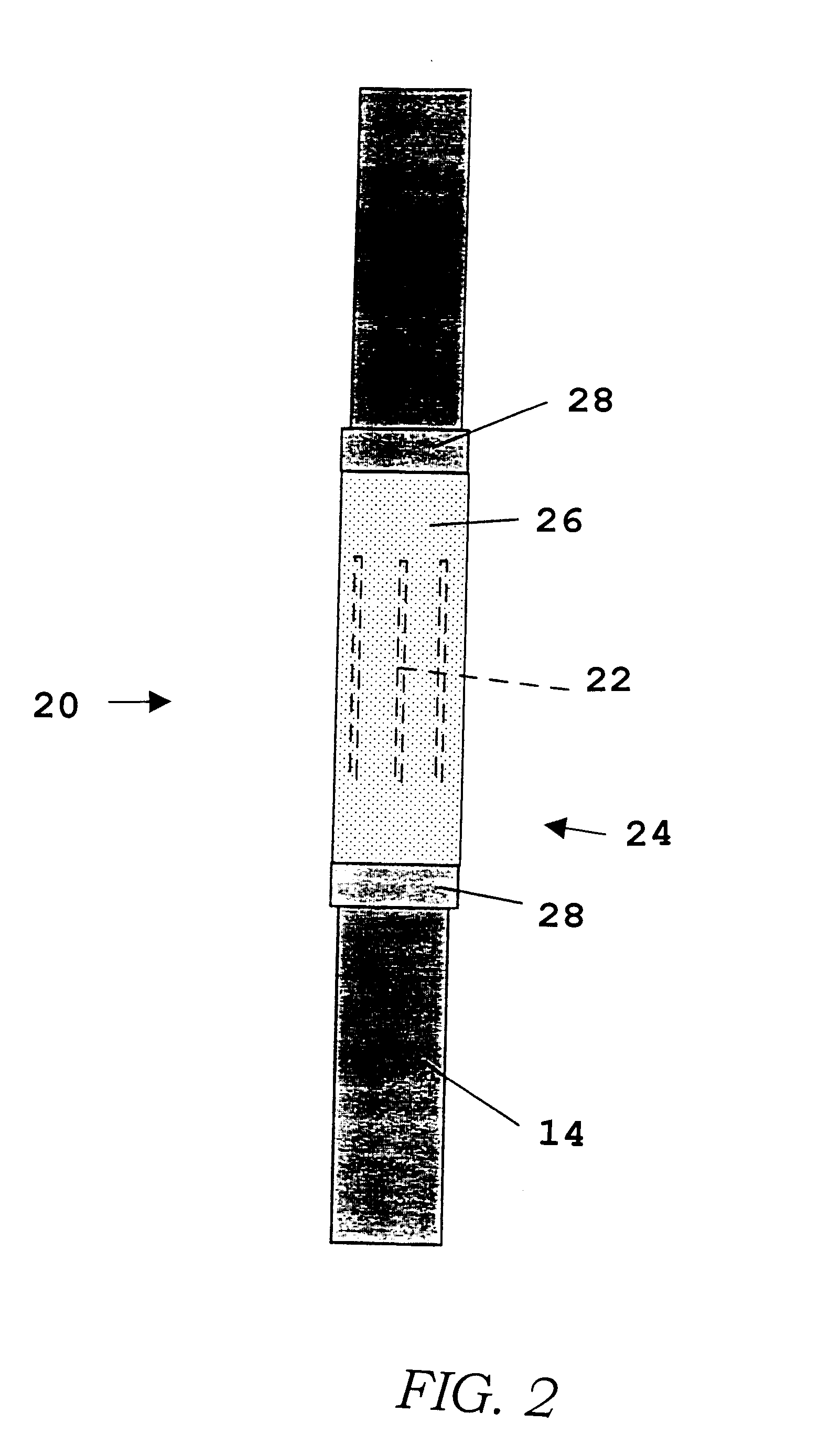
According to one embodiment of the invention, the outer casing 14 includes a slotted section 15 in which an EM receiver 16 is disposed. An EM transmitter 18 is deployed near a MWD tool (not shown), which collects drilling and geological data related to the drilling operation. The EM transmitter 18 transmits the drilling and geological data via electromagnetic waves, which are received by the EM receiver 16 through the slotted section 15 of the outer casing 14. The receiver 16 subsequently sends the received drilling and geological data...


PUM


Abstract

A system and method for enhancing the reception of electromagnetic (EM) waves in a fixed downhole receiver of an EM telemetry system is provided. In one embodiment, slots are formed in a portion of an outer casing and an EM receiver is positioned within the outer casing so as to be aligned with the slots formed therein. In another embodiment, an inductive coupling arrangement is provided to transfer signals from an EM receiver mounted on the outside surface of an outer casing to a wireline that is attached to the outer surface of an inner casing, which is disposed within the outer casing. In yet another embodiment, an insulated gap is formed in the surface of the outer casing. An EM receiver, mounted on the outer surface of the inner casing, is positioned above the insulated gap of the outer casing. An electrical coupling mechanism is further provided to electrically couple the inner and outer conductors at a point above the EM receiver.

Description

1. Field of the InventionThe present invention relates generally to electromagnetic (EM) telemetry, and, more particularly, to a method and apparatus for facilitating EM wave reception of drilling and geological data in a fixed downhole receiver of an EM telemetry system. The invention has general application in the field of hydrocarbon exploration and production.2. Description of Related ArtIn standard practice, EM telemetry systems transmit drilling and geological data from downhole tools, such as a measurement-while-drilling (MWD) tool, to a location at the surface for analysis. The drilling and geological data usually provides important information regarding any potential problems that may occur during downhole operations. For example, the data characterizing the downhole conditions may indicate the production of water or sand, in which case, immediate notification of such is desired in order that corrective action may be taken. Accordingly, it is important to receive this downh...

Claims


Application Information

Patent Timeline
Patent Type & Authority Patents(United States)
IPC IPC(8): E21B47/12
CPCE21B47/122E21B47/13
Inventor EDWARDS, JOHN E.CLARK, BRIANLOVELL, JOHN R.
Owner SCHLUMBERGER TECH CORP
Why Eureka
Try Eureka