Fuel injection valve for internal combustion engines

a technology for internal combustion engines and fuel injection valves, which is applied in the direction of fuel injection pumps, machine/engines, operating means/releasing devices of valves, etc., can solve the problems of limiting the control capability of fuel injection events and making further optimization of injection events more difficul

Inactive Publication Date: 2004-05-11
ROBERT BOSCH GMBH
View PDF4 Cites 17 Cited by
  • Summary
  • Abstract
  • Description
  • Claims
  • Application Information

AI Technical Summary

Problems solved by technology

A hydraulically adjustable stroke stop of this type has a black-and-white function; that is, it does not allow any graduations between the two o

Method used


Image

  • Fuel injection valve for internal combustion engines
  • Fuel injection valve for internal combustion engines
  • Fuel injection valve for internal combustion engines

Examples


Embodiment Construction

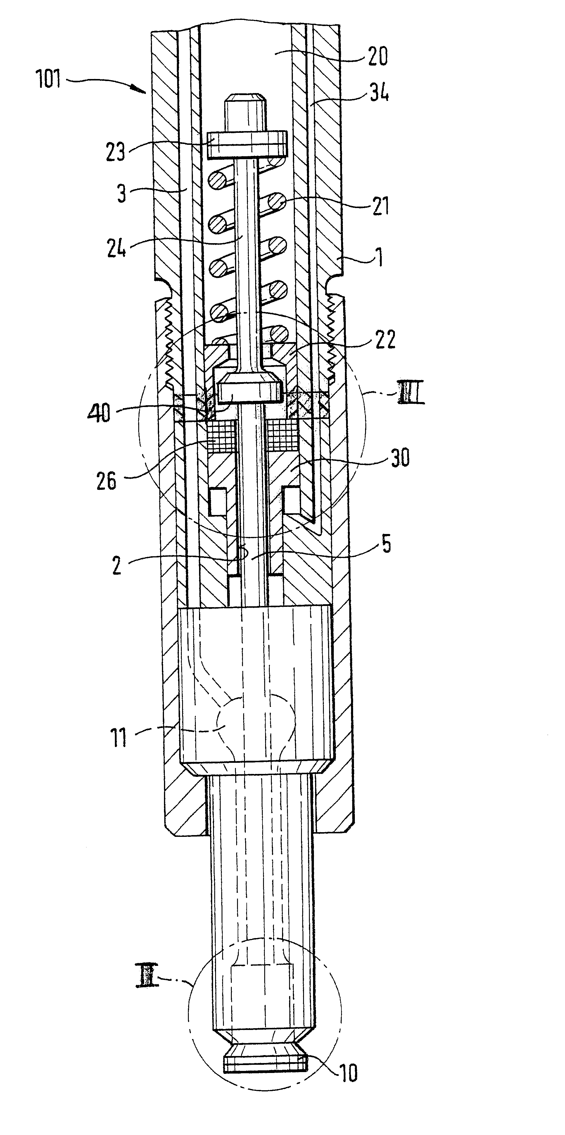
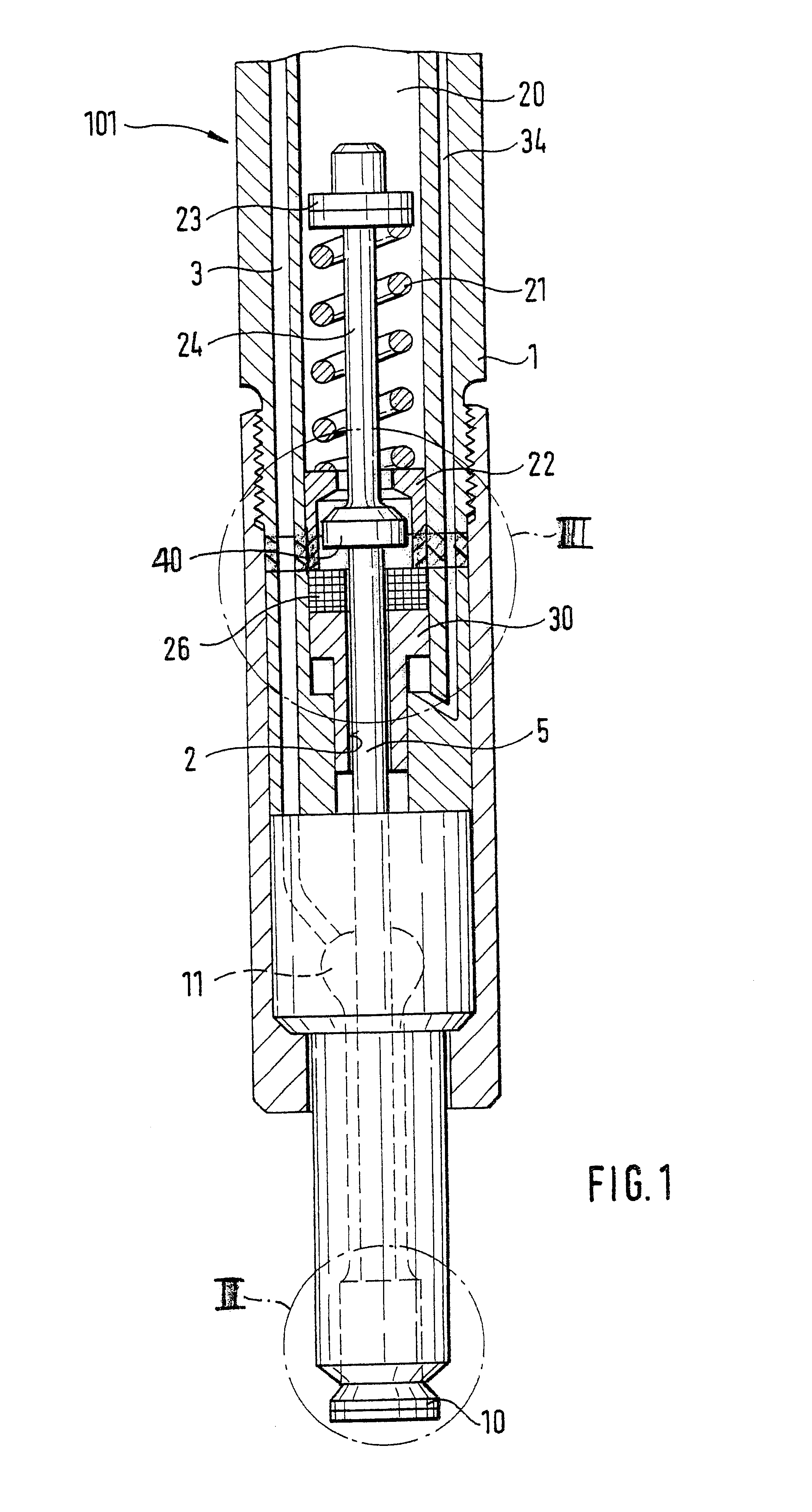
FIG. 1 shows a fuel injection valve for internal combustion engines of the outward-opening type. In a valve body 1, which can be constructed in multiple parts, a bore 2 is made in which a piston like valve member 5 is disposed, which is axially movable counter to the force of a closing spring 21. In a portion, shown at the top in FIG. 1, of the bore 2 that is remote from the combustion chamber, the valve member 5 is guided, while the portion of the valve member 5 remote from the combustion chamber and shown at the bottom in FIG. 1 is surrounded by a pressure chamber 11, which can be made to communicate with a high-pressure fuel source via an inlet conduit 3 embodied in the valve body 1. The valve member 5 merges toward the combustion chamber with a larger-diameter closing head 10, which is guided in a larger-diameter portion of the bore 2.

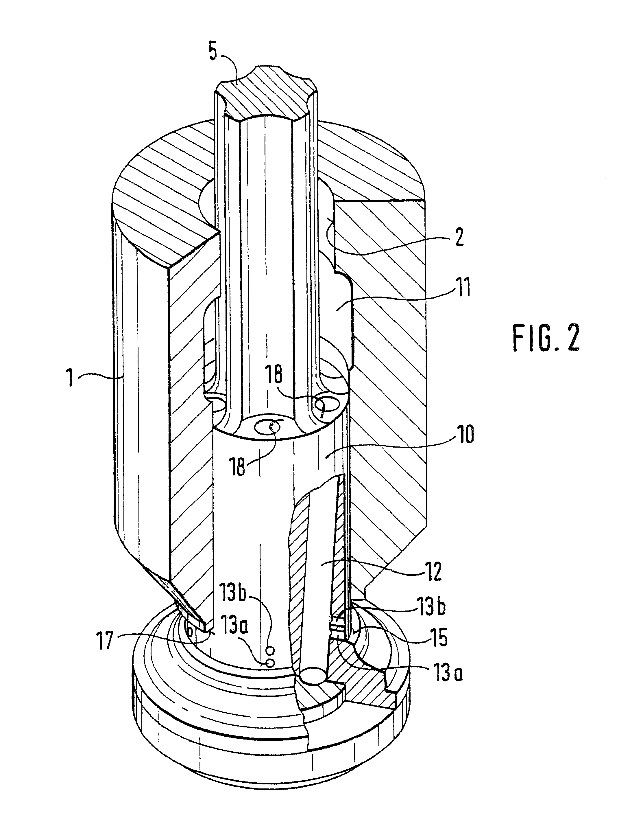
In FIG. 2, an enlarged view of the closing head 10 and the surrounding valve body 1 is shown. On the outer wall of the closing head 10, two rows o...


PUM


Abstract

A fuel injection valve has a valve body and a valve member axially movable within the valve body. The opening stroke of the valve member is limited by a stroke stop face provided on a control piston which surrounds the valve member. A control chamber, which may be filled with fuel, is located at one end of the control piston. At a certain pressure in the control chamber, the control piston moves from a first to a second stroke position to limit the opening stroke motion of the valve member. Part of the control piston is embodied as a piezoelectric actuator which, when supplied with electric current, changes its axial length to further vary the stroke of the valve member.

Description

PRIOR ARTThe invention is based on a fuel injection valve for internal combustion engines as generically defined by the preamble to claim 1. One such fuel injection valve, known from German Patent Disclosure DE 196 23 211 A1, has a valve body in which, in a bore, a piston like valve member is disposed such that it is movable axially counter to the force of a closing spring. On the end toward the combustion chamber, the valve member changes over into a closing head, which is guided in the bore. In the outward-oriented opening stroke motion of the valve member, the closing head emerges from the bore, and a control edge embodied on the closing head uncovers at least one injection opening. A plurality of injection openings can also be provided, which are opened successively by the control edge. As a result, by a limitation of the opening stroke of the valve member to a partial stroke, it becomes possible to uncover only some of the injection openings or to open only a partial cross sect...

Claims


Application Information

Patent Timeline
IPC IPC(8): F02M61/08F02M61/00F02M61/18F02M61/16F02M61/04F02M63/00F02M51/06F02M61/06F02M61/10
CPCF02M61/045F02M61/08F02M61/161F02M61/182F02M63/0003F02M63/0007F02M2200/21
Inventor HARN DORF, HORST
Owner ROBERT BOSCH GMBH
Why Eureka
Try Eureka