
Water treatment method and apparatus

a technology of water treatment and wastewater treatment, applied in the direction of water/sewage treatment by oxidation, lighting and heating equipment, water treatment water, etc., can solve the problems of unsatisfactory waste disposal, all prior art methods and equipment, and high demand for purifying chemicals, so as to reduce the emission of industrial and urban waste, reduce the emission of waste, and reduce the demand for wastewater treatment volume

Inactive Publication Date: 2004-05-11
ARGAD EYAL
View PDF15 Cites 52 Cited by
  • Summary
  • Abstract
  • Description
  • Claims
  • Application Information

AI Technical Summary

Benefits of technology

As will be appreciated by the skilled person, the COD of the make-up stream, at high COD values, is typically not less than about 600 and only at peak times reaches over 2,000 ppm. Normally, however, the COD of the make-up stream is maintained between 500 and 1000 ppm. As will be appreciated by the skilled person, the invention is not limited to CODs of 500 and above, and can of course operate at lower CODs. However, the advantages attained by the invention are even more enhanced when high CODs, or 500 or more are used, which are unheard of in the art of operating cooling towers.

Problems solved by technology

However, all prior art methods and apparatus suffer from the severe drawback that they require, in order to operate, to utilize substantially non-polluted water, since the addition of impure water leads to operational problems, to high purifying chemicals demand, and to undesirable disposal of waste.
Particularly undesired, according to the known art, is the use of water containing organic contaminants.
Thus, essentially clean water is wasted, e.g., for operating cooling towers, while waste water from the tower and other industrial or urban sources has to be treated prior to disposal, in an expensive manner.
Cooling towers cannot use water with a high content of organic and biologic materials, since the resulting biofouling, developing as a matter of hours, initially reduces the efficiency of the tower, and eventually may lead to a clogging of the tower's fill.

Method used


Image

  • Water treatment method and apparatus
  • Water treatment method and apparatus

Examples


Embodiment Construction

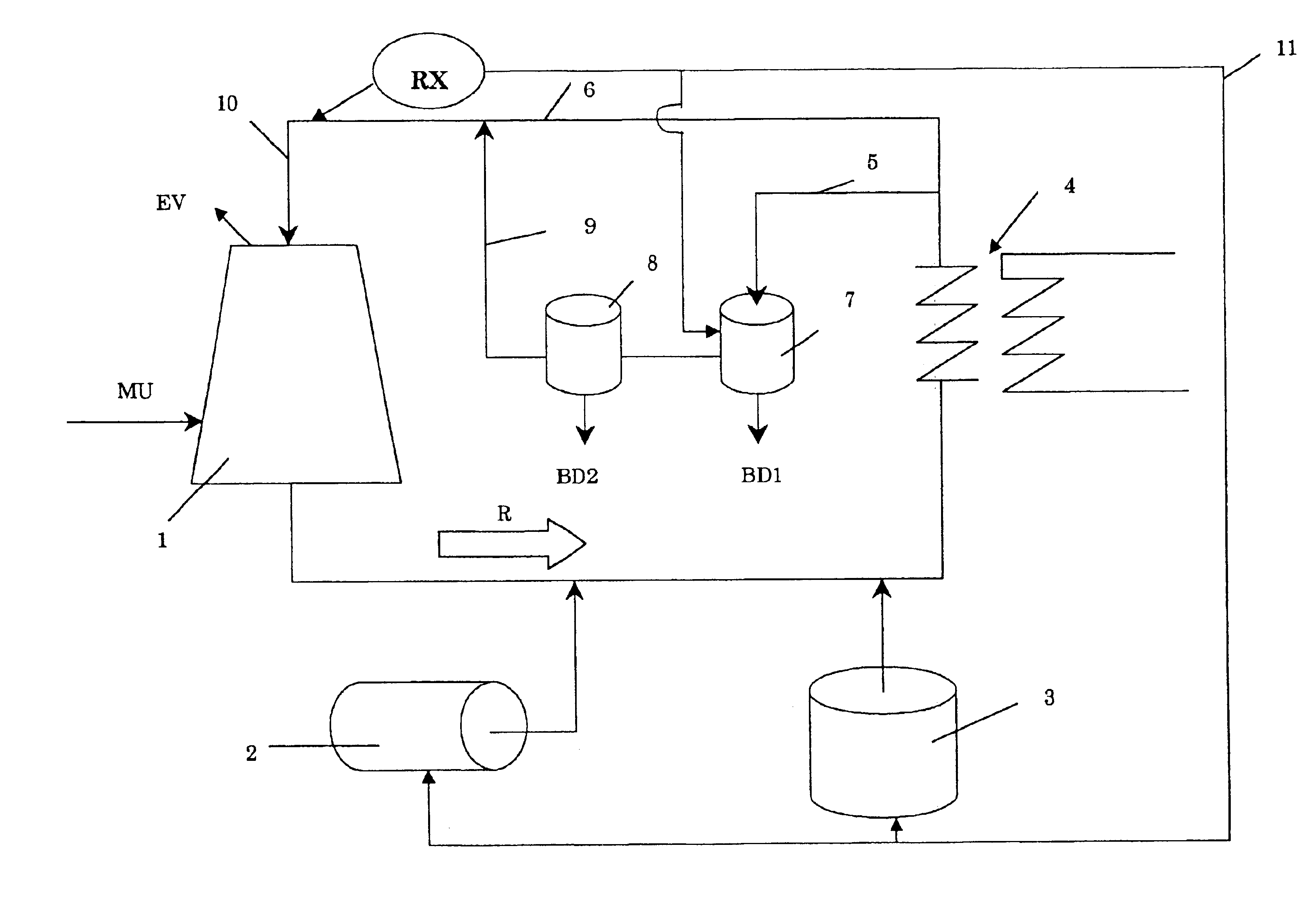
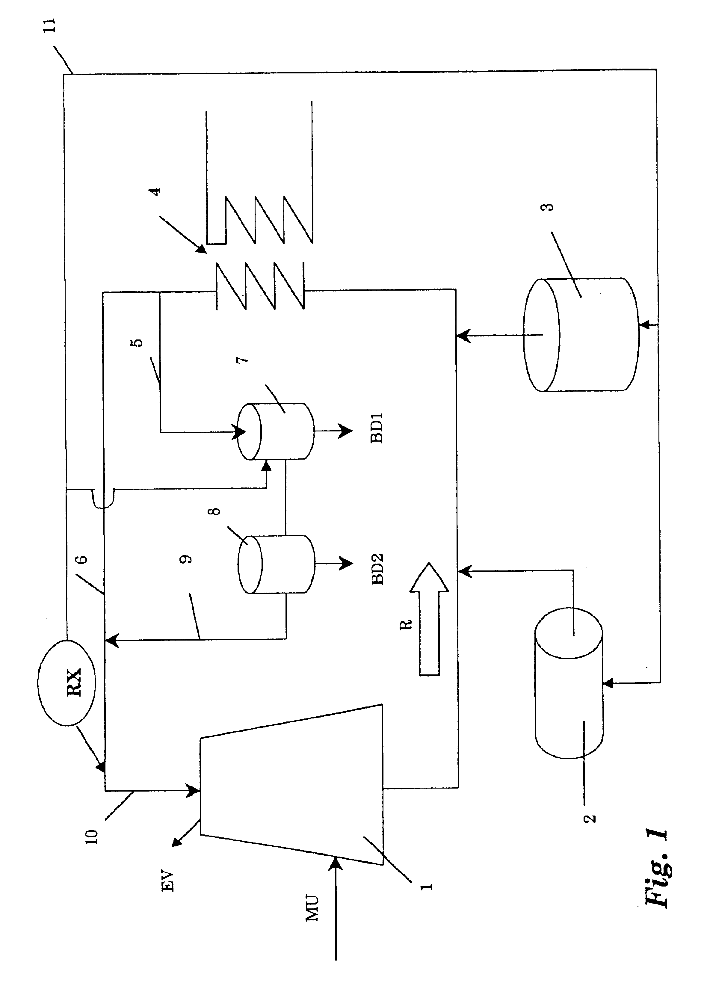
The invention will now be illustrated with reference to FIG. 1. Specific operational data will be provided below, for the purpose of illustration, it being understood that any values are given as exemplary values, in order to better illustrate the invention, but the invention is of course not limited to any particular operating conditions. In the figure, numeral 1 indicates the cooling tower, which operates with a make-up feed, MU, which in the example is 15 m.sup.3 / hr. The MU stream may contain a high content of organic contaminants, such as a stream having a chemical oxygen demand (COD) of about 500-1000 ppm. It should also be noted that the COD may, at peak values, exceed 2000 ppm. When the COD increases, it is desirable to employ non-oxidizing biocides, e.g., chlorinated phenol, to assist in reducing and preventing biofouling. This, as will be apparent to the skilled person, is a concentration by far higher than acceptable according to the prior art. Still, when operating accor...


PUM

PropertyMeasurementUnit
heightaaaaaaaaaa
diameteraaaaaaaaaa
diameteraaaaaaaaaa

Abstract

A method of operating a cooling tower comprises feeding to the cooling tower a make-up stream of water containing organic and / or biological contaminants, causing a side stream taken from the recirculating stream to pass through an electrolytic cell, removing solids precipitating by the action of the cell, and remixing the treated side stream with the main stream, before feeding them to the cooling tower.

Description

FIELD OF THE INVENTIONThe present invention relates to water treating systems. Particularly, the invention relates to a method and apparatus for the utilization of wastewater.BACKGROUND OF THE INVENTIONThe problem of scale is inherent to all systems in which there is a flow of water that contains any of Ca.sup.++ and Mg.sup.++ ions together with any of OH., CO.sub.3.dbd., HCO.sub.3 --, SiO.sub.3.dbd., SO.sub.4.dbd. or PO.sub.4.dbd.. Under certain temperature and pH conditions, carbonates, silicates, sulfates, phosphate and hydroxide salts precipitate and cause blockage of nozzles, reduction of cross-section area of pipes, heat insulation and underdeposit corrosion. The well-known methods of removing scale from aqueous liquids are reverse osmosis and ion exchange. Another method for removing scale is direct current (DC) electrolysis. U.S. Pat. No. 4,384,943 discloses a method of fluid treatment which comprises applying DC current to aqueous liquids.Electrolytic treatment of aqueous f...

Claims


Application Information

Patent Timeline
Patent Type & Authority Patents(United States)
IPC IPC(8): C02F1/461F28F25/00C02F1/76C02F1/50
CPCC02F1/461F28F25/00C02F1/50C02F1/76C02F2103/023C02F2209/04C02F2209/08
Inventor ITZHAK, DAVID
Owner ARGAD EYAL
Learn More