This helps you quickly interpret patents by identifying the three key elements:
Problems solved by technology
Method used
Benefits of technology
Benefits of technology
In a thin film magnetic head of the invention, a signal magnetic field of the magnetic medium is captured by the projecting portion of the stack. Therefore, the number of magnetic layers of the stack can be increased without increasing a length (sometimes called a magnetic gap length) of a signal magnetic field capturing surface along the direction of stacking of the stack. Accordingly, the rate of resistance change and resistance can be increased.
In a further thin film magnetic head of the invention, a magnetic path extending from the projecting portion of the stack toward at least one of the shield layers is formed. Therefore, the signal magnetic field easily extends throughout the stack.
In a magnetic transducer of the invention, the signal magnetic field of the magnetic medium is captured by the projecting portion of the stack. Therefore, the number of magnetic layers of the stack can be increased without increasing the length (the magnetic gap length) of the signal magnetic field capturing surface along the direction of stacking of the stack.
Problems solved by technology
However, shot noise is caused and thus the S / N (signal to noise) ratio becomes low.
Consequently, the tunnel junction type GMR film has the limitations of improvement in properties of the magnetic head.
Consequently, there is a problem that the heretofore-reported rate of resistance change of 10% to 15% of the CPP structure is insufficient.
Thus, there is a problem of inadaptability to high-density recording.
When the length is more than 0.1 .mu.m, it is difficult to capture the signal magnetic field.
On the other hand, when the antiferromagnetic film is made of the non-heat-treatment type antiferromagnetic material, heat treatment for the heat-treatment type antiferromagnetic material is unnecessary.
Method used
Image
Click on the blue label to locate the original text in one second.
Reading with bidirectional positioning of images and text.
Examples
second embodiment
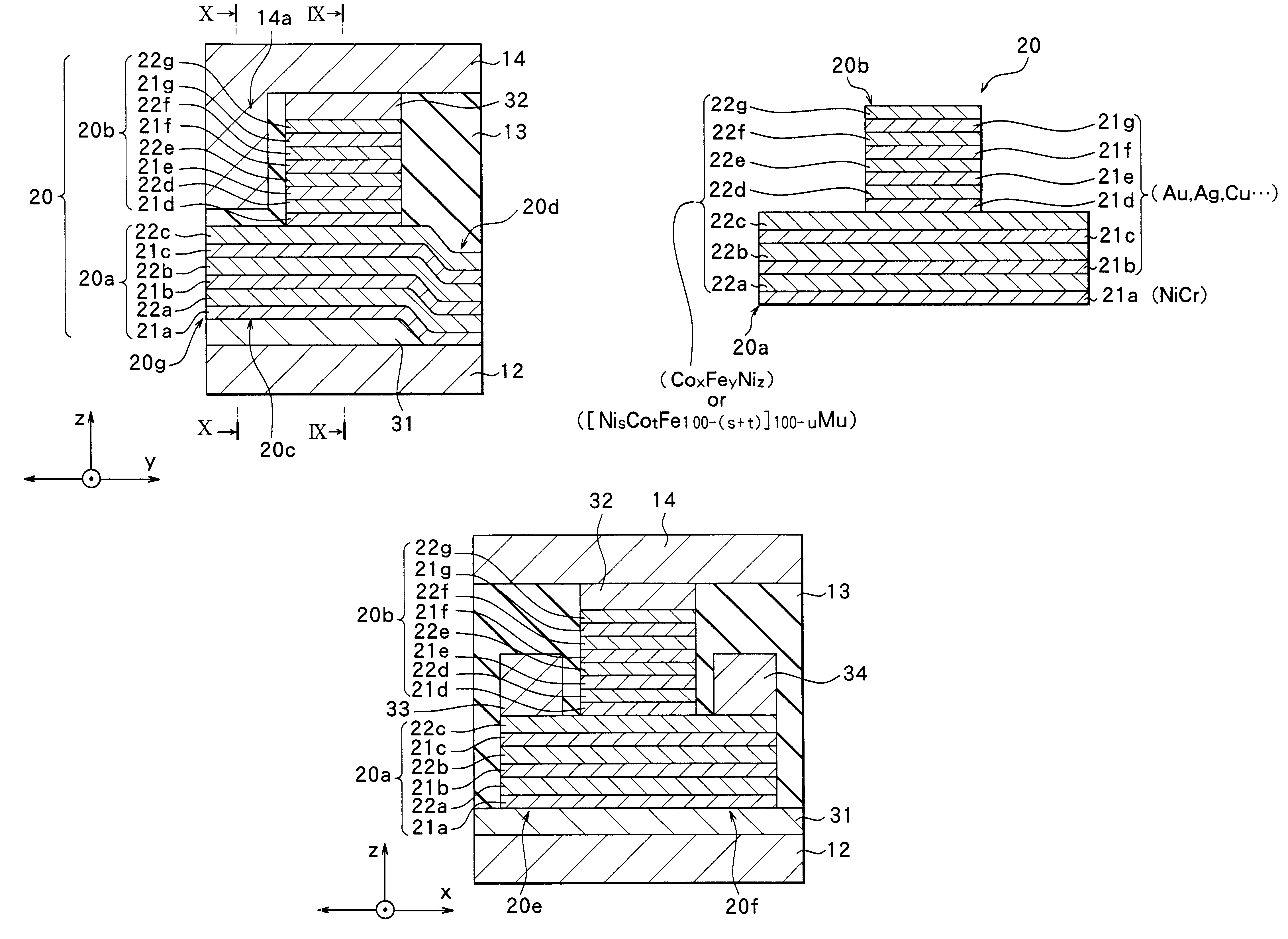
Next, a second embodiment of the invention will be described with reference to FIG. 16. A thin film magnetic head according to the second embodiment is the same as the thin film magnetic head according to the first embodiment except that nonmagnetic layers 121b to 121g of a stack 120 are made of other materials. Accordingly, only the stack 120 is shown in FIG. 16. The same structural components as the structural components of the first embodiment are indicated by the same reference numerals, and the detailed description thereof is omitted.
In the stack 120 of the embodiment, it is preferable that the nonmagnetic layers 121b to 121g are made of a material containing Ni and Cr. Specifically, it is preferable that the nonmagnetic layers 121b to 121g are made of (Ni.sub.a Cr.sub.100-a).sub.b A.sub.100-b similarly to the underlayer 21a, where A, a and b are as mentioned in the description of the first embodiment. The composition of each of the nonmagnetic layers 121b to 121g may be identi...
third embodiment
Next, a third embodiment of the invention will be described with reference to FIG. 17. A thin film magnetic head according to the third embodiment is the same as the thin film magnetic head according to the first embodiment except that the material or composition of magnetic layers 222a to 222c included in a first region 220a of a stack 220 differs from the material or composition of magnetic layers 222d to 222g included in a second region 220b. Accordingly, only the stack 220 is shown in FIG. 17.
Preferably, the magnetic layers 222a to 222c of the first region 220a are made of, for example, a material containing at least Ni in a group consisting of Ni, Co, Fe, Cr, Ta, Rh, Mo, Zr and Nb. Specifically, it is preferable that the magnetic layers 222a to 222c are made of [Ni.sub.s Co.sub.t Fe.sub.100-(s+t) ].sub.100-u M.sub.u, where s, t and u are as mentioned in the description of the first embodiment.
Preferably, the magnetic layers 222d to 222g of the second region 220b are made of, fo...
fourth embodiment
Next, a fourth embodiment of the invention will be described with reference to FIG. 18. A thin film magnetic head according to the fourth embodiment is the same as the thin film magnetic head according to the third embodiment except that the material or composition of nonmagnetic layers 321b and 321c included in a first region 320a of a stack 320 differs from the material or composition of nonmagnetic layers 321d to 321g included in a second region 320b. Accordingly, only the stack 320 is shown in FIG. 18.
In the stack 320 of the embodiment, it is preferable that the nonmagnetic layers 321b and 321c included in the first region 320a are made of a material containing Ni and Cr. Specifically, it is preferable that the nonmagnetic layers 321b and 321c are made of (Ni.sub.a Cr.sub.100-a).sub.b A.sub.100-b, where A, a and b are as mentioned in the description of the first embodiment. The composition of each of the nonmagnetic layers 321b and 321c may be identical with or different from th...
PUM
Abstract
An object of the invention is to provide a thin film magnetic head and a magnetic transducer, which can obtain resistance properties adaptable to ultra-high-density recording. The thin film magnetic head has a stack including a plurality of magnetic layers stacked alternately with a plurality of nonmagnetic layers. The stack is divided into a first region and a second region in a direction of stacking. The first region comprises a projecting portion projecting toward a magnetic medium, an extending portion extending in the direction opposite to the projecting portion, and a pair of wide portions widened in the direction perpendicular to the direction in which the extending portion extends. An end surface of the projecting portion is exposed to the outside and faces the magnetic medium. Thus, the end surface functions as a magnetic field capturing portion for capturing a signalmagnetic field of the magnetic medium. The stack has the projecting portion, and the projecting portion functions as the magnetic field capturing portion. Thus, the number of layers of the stack can be increased without increasing a length of a surface facing the magnetic medium. Therefore, the rate of resistance change and the resistance can be increased.
Description
1. Field of the InventionThe invention relates to a thin film magnetic head and a magnetic transducer for use in the same. More particularly, the invention relates to a thin film magnetic head and a magnetic transducer which can obtain resistance properties adaptable to ultra-high-density recording.2. Description of the Related ArtRecently, an improvement in performance of a thin film magnetic head has been sought in accordance with an increase in a surface recording density of a hard disk or the like. A composite thin film magnetic head, which has a stacked structure comprising a reproducing head having a magnetoresistive element (hereinafter referred to as an MR element) that is a type of magnetic transducer and a recording head having an inductive magnetic transducer, is widely used as the thin film magnetic head.MR elements include an element using a magnetic film (an AMR film) exhibiting an anisotropic magnetoresistive effect (an AMR effect), and an element using a magnetic fil...
Claims
Application Information
Patent Timeline
Application Date:The date an application was filed.
Publication Date:The date a patent or application was officially published.
First Publication Date:The earliest publication date of a patent with the same application number.
Issue Date:Publication date of the patent grant document.
PCT Entry Date:The Entry date of PCT National Phase.
Estimated Expiry Date:The statutory expiry date of a patent right according to the Patent Law, and it is the longest term of protection that the patent right can achieve without the termination of the patent right due to other reasons(Term extension factor has been taken into account ).
Invalid Date:Actual expiry date is based on effective date or publication date of legal transaction data of invalid patent.

