Method and apparatus for switching between input clocks in a phase-locked loop

Inactive Publication Date: 2004-05-25
XENOGENIC DEV LLC
View PDF4 Cites 79 Cited by
  • Summary
  • Abstract
  • Description
  • Claims
  • Application Information

AI Technical Summary

Problems solved by technology

Phase changes in the output clock due to switching input clocks can lead to problems such as transmission errors.
However, low bandwidth PLLs suitable for meeting ti

Method used


Image

  • Method and apparatus for switching between input clocks in a phase-locked loop
  • Method and apparatus for switching between input clocks in a phase-locked loop
  • Method and apparatus for switching between input clocks in a phase-locked loop

Examples


Example

)

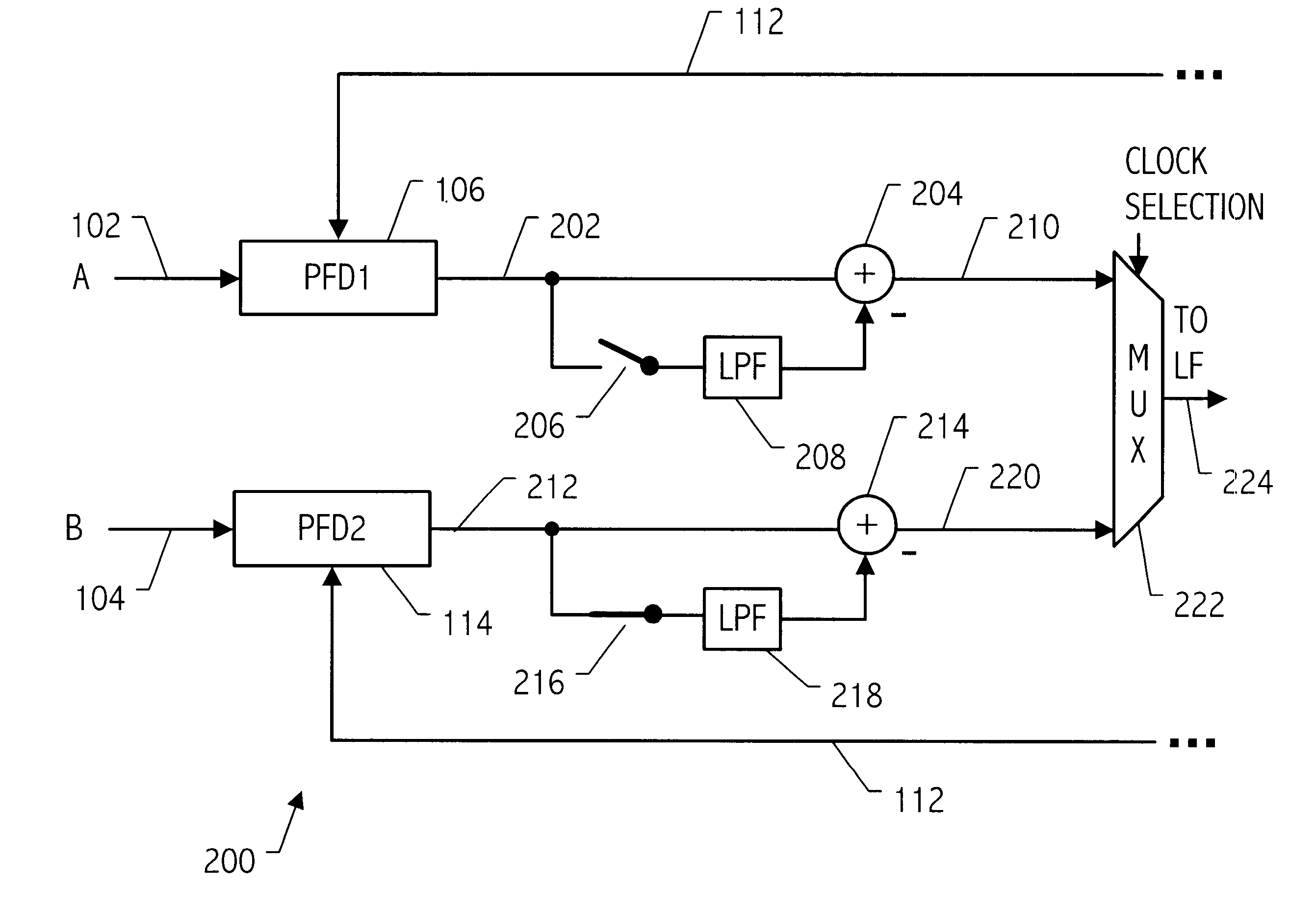
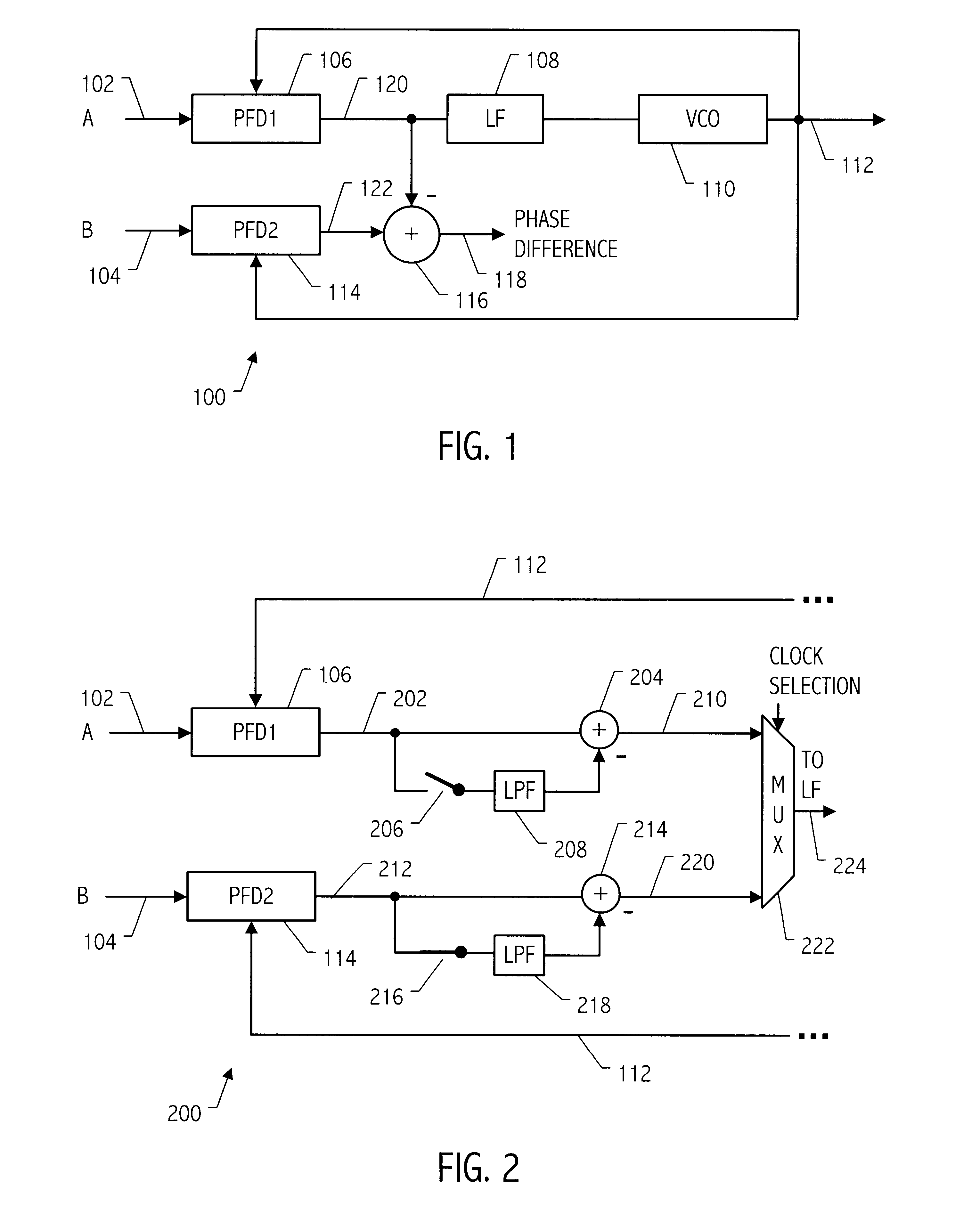
Referring to FIG. 1, a phase-locked loop (PLL) 100 receives two input clocks designated as clock A 102 and clock B 104, either of which may be utilized as the input clock by the phase-locked loop 100. Conceptually, the phase difference between the input clocks is monitored and stored. When an event occurs that causes the input clock being utilized by PLL 100 to switch, the known phase difference is utilized to compensate for that difference. As shown in FIG. 1, each clock input is provided with a phase / frequency detector 106 and 114 for monitoring the phase difference at any given time between the respective input clocks A and B and the PLL output 112. Phase / frequency detector 106 monitors the phase difference between the PLL output 112 and the input clock A 102 and phase / frequency detector 114 monitors the phase difference between the output 112 and the input clock B 104. A loop filter 108 and voltage controlled oscillator (VCO) 110 provide the remaining PLL functionality. Differe...


PUM


Abstract

A phase-locked loop receives multiple input clocks, one of which is selected for use by the PLL at any one time. The phase difference(s) between non-selected input clocks and a feedback signal of the PLL, is monitored and stored. When a switch occurs to using a non-selected clock as the input clock of the PLL, the stored phase difference, typically a DC offset value, is injected into the phase-locked loop to compensate for the phase difference between the clocks.

Description

1. Field of the InventionThis invention relates to phase-locked loops, and more particularly to phase-locked loops with selectable input clock signals.2. Description of the Related ArtIn optical communication systems, line cards compliant with standards such as Synchronous Optical Network (SONET) or Synchronous Digital Hierarchy (SDH) (the European counterpart to SONET), utilize clock generation circuits to generate clocks used in data transmission and reception. In such clock generation circuits, a phase-locked loop (PLL) receives an input reference clock and generates one or more high speed clocks suitable for use in transmitting or receiving data in a SONET(or SDH) based system. According to one aspect of such a communication system, multiple reference clocks may be supplied to a clock generation circuit to provide a variety of capabilities, including redundancy. When the PLL in the clock generation circuit switches from using one input reference clock to using another input refe...

Claims


Application Information

Patent Timeline
IPC IPC(8): H03L7/06H03L7/081H03L7/087H03L7/093H03L7/14H03L7/197H04J3/06
CPCH03L7/081H03L7/087H03L7/093H03L7/14H03L7/197H04J3/0688
Inventor HUANG, YUNTENGPERROTT, MICHAEL H.GARLEPP, BRUNO
Owner XENOGENIC DEV LLC
Why Eureka
Try Eureka