Working poles and method of repair

a technology of working poles and working poles, which is applied in the direction of building components, building repairs, foundation engineering, etc., can solve the problems of metal corrosion, unsafe or inability to withstand wind loads, and high cost of replacement, so as to increase the resistance to corrosion

Inactive Publication Date: 2004-06-01
YOUNG ROBERT A
View PDF15 Cites 32 Cited by
  • Summary
  • Abstract
  • Description
  • Claims
  • Application Information

AI Technical Summary

Benefits of technology

It is also an object of the present invention to provide an inexpensive means for repairing existing working poles that have been damaged by corrosion and that would otherwise require replacement.
After cutting the pole as described above, the top of the pole including the now disconnected electrical conductors, and the light or luminaire apparatus on the top thereof are removed; an internal sleeve 15 formed of a metal pipe having a smaller diameter then the diameter of the pole is inserted in the base 9 of the pole to an appropriate depth and is centered in the base and maintained in position in a manner to be described. The sleeve 15 is provided with a spacer or grommet 18 that assists in positioning the sleeve in the base of the pole and also closes the circumferential gap existing between the sleeve and the pole base. When the sleeve is held in this position, packing material such as liquid grout 16 is poured into the space between the sleeve and the pole base. The grout is allowed to set. The top portion of the pole is then replaced over the sleeve into contact with the base from which it had been removed. Where a utility opening is not available, holes can be drilled through which grout is inserted. Grout is then poured through the utility opening 20 into the space between the sleeve and the pole that extends from the cut 12 to the top of the sleeve. When the grout sets, the pole is now in its original position and is vertically supported through its base from which it had previously been separated and is supported both vertically as well as in all load directions through the utilization of the grout and the internal sleeve. Packing material such as grout solidifies or stabilizes and can therefore transfer forces to and from the sleeve and the pole. Under some circumstances even sand may fulfil the requirements of the packing material. Such material conveniently may be poured into the circumferential space between the sleeve and the base and between the sleeve and the upper portion of the pole and subsequently "set"; alternatively, the material could be pre-formed and placed about the sleeve and subsequently activated after the sleeve is inserted in the base. It is important that the packing material be capable of withstanding the forces applied to it by the pole and the sleeve, and that it remains stable without shrinking over time.
Thus, the method of the present invention includes the cutting of the pole at its base above its ground support and then inserting and positioning a sleeve within the base, pouring grout to fill the space between the sleeve and the base, replacing the top portion of the pole to its original position in contact with its base, and pouring grout between the sleeve and the top portion of the pole. When the grout sets, the pole is in its original position and is strengthened and capable of withstanding all loads for which it was designed. Further, since the grout extends around the external surfaces of the internal sleeve, it serves to protect the sleeve from corrosion which therefore provides the pole with a corrosion resistant base. In addition, the sleeve can be galvanized to further increase its resistance to corrosion.
The grout that is used in the present invention may be typical standard non-shrink grout. It is believed that grout conforming to ASTM 1107 would be appropriate, such grout is low viscosity when initially mixed and is readily pourable into the space between the sleeve and the pole; the grout, when set, bonds to the external surfaces of the sleeve as well as the internal surfaces of the pole thus creating a strong joint structure connecting the pole to its base in the repaired pole. As described previously, the internal sleeve may be chosen from a pipe having the same strength or stronger than the pole and generally is chosen to be the largest diameter possible that will fit within the existing pole while leaving an adequate grout space therebetween; the space that has been found appropriate is generally approximately 1 / 2". The length of the sleeve must be sufficient to provide appropriate structural strength to the repaired pole; it is believed that the sleeve should extend into the base a distance of approximately 3 diameters of the pole and an equal distance into the upper portion of the pole. However, it is believed that a significantly shorter length may be adequate in many circumstances and may be as short as twice the diameter of the pole extending into the base and extending into the upper portion for the pole.

Problems solved by technology

While steel poles of the past have typically included an anti-corrosion surface such as asphaltic paint, the moisture in the soil through the years eventually penetrates the protective coating and causes corrosion of the metal.
Over time the corrosion seriously degrades the strength of the pole rendering the pole unsafe or unable to withstand wind loads to which it is subjected.
When such corrosion occurs, it becomes incumbent upon the utility or municipal entity to replace the poles; such replacement is time consuming and very expensive.
The expense and difficulty is exacerbated when concrete such as sidewalks or pavement exists around the base of the pole thus requiring removal and subsequent replacement of not only the pole but also the sidewalk or pavement.

Method used


Image

  • Working poles and method of repair
  • Working poles and method of repair

Examples


Embodiment Construction

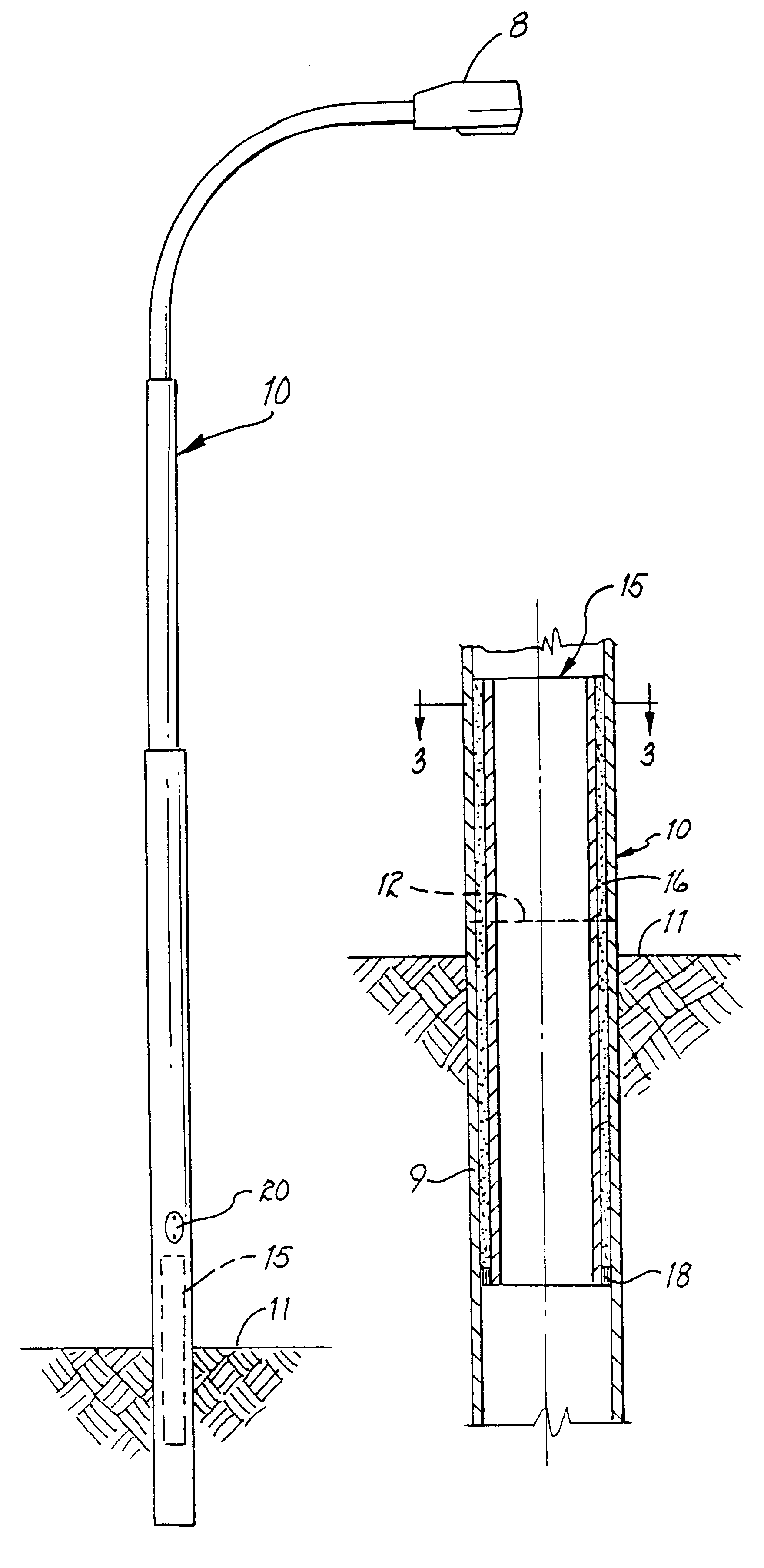
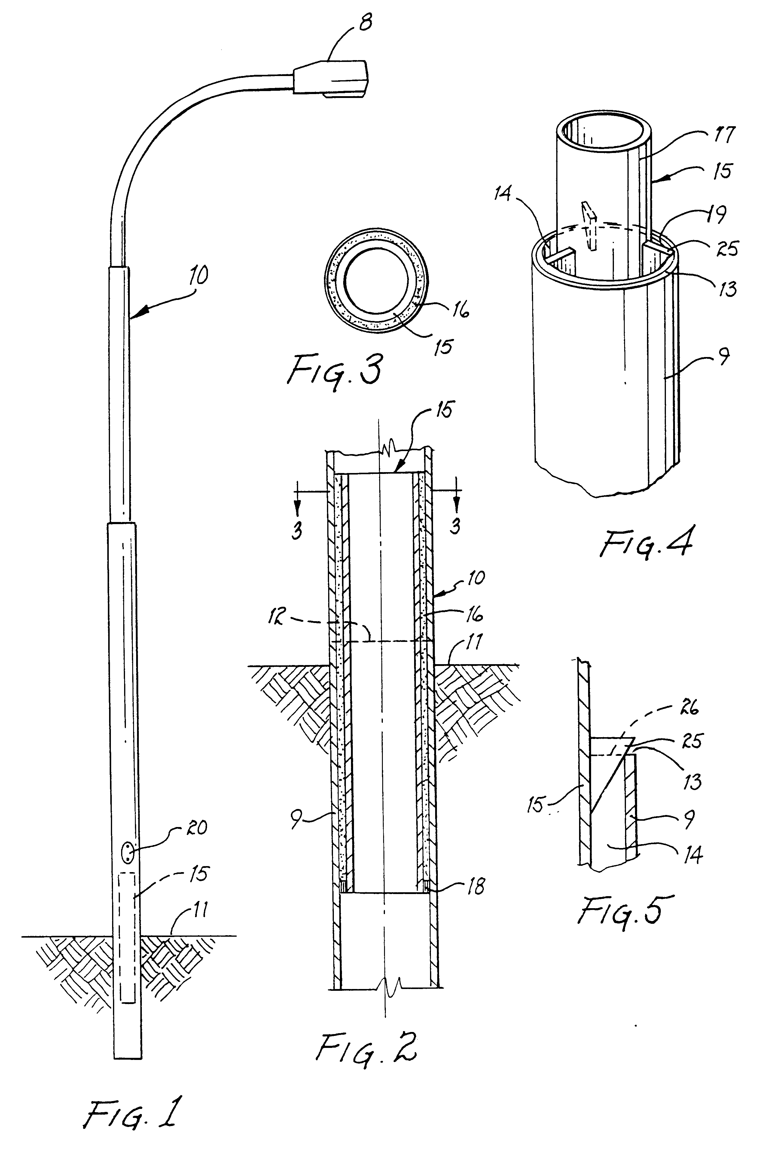
luminaire pole was repaired by entering the utility opening therein and unplugging the electrical wires extending upwardly through the luminaire pole to the top thereof. A band saw was then used to cut through the base of the pole approximately 2" above grade level. The top of the pole was then removed leaving the base of the pole extending upwardly from the ground. The pole was formed of steel pipe of a typical 5" nominal OD (5.563") conforming to a typical ASTM A53 specification found in older luminaire poles. The pole had an asphaltic paint on it, the pipe had a nominal 3 / 16" thickness. A sleeve was chosen having a 41 / 2" outside diameter and a wall thickness of 0.237". The chosen sleeve was cut to a length of 34 inches. A gasket formed of a foam rubber strip having an adhesive backing and being 11 / 4" wide and 1 / 8" thick was wound about the sleeve adjacent one end thereof until the thickness of the gasket formed thereby was slightly larger than the inside diameter of the base of t...


PUM


Abstract

A hollow working pole such as a luminaire pole is repaired by cutting the pole above ground level and inserting a sleeve. The sleeve is maintained in position while grout is poured to fill the space between the sleeve and the inner surfaces of the pole base. The top portion of the pole, previously removed, are replaced and grout is poured into the circumferential space between the insert and the inner surfaces of the upper portion of the pole.

Description

The present invention relates to a method and apparatus for repairing working poles such as luminaire poles, flag poles, utility poles and the like. More specifically, the invention is directed to those types of poles that are erected with the base portions thereof extending directly into the ground.Working poles such as luminaire poles are typically constructed of hollow pipe usually made of steel although aluminum, bronze or in some cases fiberglass are used. For several years cities and utility companies have utilized metal poles that are erected to a vertical position and are simply supported by drilling or excavating a hole in the ground, inserting the pole, and then compacting the soil around the base of the pole. While steel poles of the past have typically included an anti-corrosion surface such as asphaltic paint, the moisture in the soil through the years eventually penetrates the protective coating and causes corrosion of the metal. The length of time before such corrosio...

Claims


Application Information

Patent Timeline
Patent Type & Authority Patents(United States)
IPC IPC(8): E04G23/02E04C3/30E04H12/22
CPCE04C3/30E04G23/0218E04H12/2292E04G23/0225
Inventor YOUNG, ROBERT A.
Owner YOUNG ROBERT A
Why Eureka
Try Eureka