Magnetic random access memory using schottky diode

a random access memory and diode technology, applied in the field of magnetic random access memory, can solve the problems of difficult to achieve complicated device structure, and affecting the thermal reliability of the mtj cell, and achieve the effect of high integration of the devi

Inactive Publication Date: 2004-06-15
SK HYNIX INC
View PDF3 Cites 52 Cited by
  • Summary
  • Abstract
  • Description
  • Claims
  • Application Information

AI Technical Summary

Benefits of technology

Presently, a magnetic random access memory (MRAM) using a Schottky diode is disclosed that allows high integration of the device by constructing the memory device with a plurality of diodes and a plurality of resistance-varying devices. In particular, an MRAM having a semiconductor layer between an MTJ cell and a bit line is utilized.

Problems solved by technology

When the diode 19 is formed using the doped polysilicon layer, the diode 19 is deteriorated at a temperature higher than a predetermined temperature, which destroys thermal reliability of the MTJ cell.
As a result, the structure of the device is complicated, and high integration of the device is difficult to achieve.
As described above, since the conventional MRAM is formed by using one PN junction diode and one MTJ cell, which is a resistance-varying device, only two bits are stored in one cell, making it difficult to achieve high integration of the device.
Moreover, the connection layer must be formed to prevent the properties of the device from being deteriorated due to the high temperature thermal process, thereby complicating the structure of the device and deteriorating the properties of the device.
In addition, high integration of the device is difficult to achieve.

Method used


Image

  • Magnetic random access memory using schottky diode
  • Magnetic random access memory using schottky diode
  • Magnetic random access memory using schottky diode

Examples


second embodiment

FIG. 4 is a cross-sectional diagram illustrating an MRAM in accordance with a Referring to FIG. 4, a word line 73 is formed on a semiconductor substrate 71, and a first MTJ cell 75, a first doped polysilicon layer 77 and a first bit line 79 are sequentially formed on the word line 73. Here, a metal layer comprising the first bit line 79 on the first doped polysilicon layer 77 or a metal layer (not shown) on the top portion of the first MTJ cell 75 below the first doped polysilicon layer 77 is used as a metal electrode for forming a schottky barrier. In general, the first MTJ cell 75 has a stacked structure of a pinned ferromagnetic layer (not shown), a tunnel oxide film (not shown) and a free ferromagnetic layer (not shown). The tunnel oxide film is formed of Al.sub.2 O.sub.3, and the pinned ferromagnetic layer and the free ferromagnetic layer are formed of an alloy mainly composed of Pt, Ni, Mn, Co and Fe.

A planarized first interlayer insulating film 81 is formed to cover the stac...

third embodiment

FIG. 5 is a cross-sectional diagram illustrating the MRAM in accordance with the present disclosure.

Referring to FIG. 5, a word line 113 is formed on a semiconductor substrate 111 and a first MTJ cell 115, a semiconductor layer 117 and a bit line 119 are sequentially formed on the word line 113. Here, a metal layer comprising the bit line 119 on the semiconductor layer 117 or a metal layer (not shown) on the top portion of the MTJ cell 115 below the semiconductor layer 117 is used as a metal electrode for forming a Schottky barrier. In general, the MTJ cell 115 has a stacked structure of a pinned ferromagnetic layer (not shown), a tunnel oxide film (not shown) and a free ferromagnetic layer (not shown). The tunnel oxide film is formed of Al.sub.2 O.sub.3, and the pinned ferromagnetic layer and the free ferromagnetic layer are formed of an alloy mainly composed of Pt, Ni, Mn, Co and Fe.

A planarized interlayer insulating film 121 is formed to cover the stacked structure of the MTJ cel...

fourth embodiment

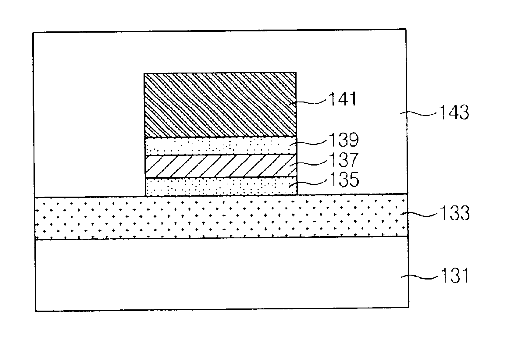
FIG. 6 is a cross-sectional diagram illustrating a MRAM in accordance with the present disclosure. Referring to FIG. 6, a word line 133 is formed on a semiconductor substrate 131 and a first semiconductor layer 135, a first MTJ cell 137, a second semiconductor layer 139 and a bit line 141 are sequentially formed on the word line 133. Here, a metal layer comprising the bottom layer of the MTJ cell 137 on the first semiconductor layer 135 or a metal layer comprising the word line below the first semiconductor layer 135 is used as a metal electrode for forming a Schottky barrier. In addition, a metal layer composing the bit line 141 on the second semiconductor layer 139 or a metal layer (not shown) of the top portion of the MTJ cell 137 below the second semiconductor layer 139 is employed as the metal electrode for forming the Schottky barrier. In general, the MTJ cell 137 has a stacked structure of a pinned ferromagnetic layer (not shown), a tunnel oxide film (not shown) and a free fe...


PUM


Abstract

A magnetic random access memory (MRAM) using a Schottky diode is disclosed. In order to achieve high integration of the memory device, a word line is formed on a semiconductor substrate without using a connection layer and a stacked structure including an MTJ cell, a semiconductor layer and a bit line is formed on the word line, thereby forming the Schottky diode between the MTJ cell and the bit line. As a result, a structure of the device is simplified, and the device may be highly integrated due to repeated stacking.

Description

1. Technical FieldThe present invention relates to a magnetic random access memory (abbreviated as `MRAM`) and, in particular, to an improved MRAM having a higher speed than a SRAM, integration as high as a DRAM, and a property of a nonvolatile memory such as a flash memory, and connecting a plurality of resistance transfer devices to one diode.2. Description of the Related ArtMost of the semiconductor memory manufacturing companies have developed MRAM's using a ferromagnetic material as the next generation of memory devices.The MRAM is a memory device for reading and writing information by forming multi-layer ferromagnetic thin films and sensing current variations according to a magnetization direction of the respective thin films. The MRAM has a high speed, low power consumption and high integration density due to the special properties of the magnetic thin film, and performs a nonvolatile memory operation such as a flash memory.The MRAM utilizes either a giant magneto resistive (...

Claims


Application Information

Patent Timeline
Patent Type & Authority Patents(United States)
IPC IPC(8): G11C11/15G11C11/02H01L27/095H01L27/105H01L27/085H01L43/08H01L21/8239H01L21/8246H01L27/22H01L29/872
CPCH01L27/224H10B61/10G11C11/15
Inventor KIM, CHANG SHUK
Owner SK HYNIX INC
Why Eureka
Try Eureka