Process for forming microporous metal parts
a technology of microporous metal parts and molding processes, which is applied in the direction of mechanical equipment, textiles and papermaking, transportation and packaging, etc., can solve the problems of large pore size of metal parts produced using this technique, uncontrollable porosity generated by this method, and varies in uniformity and size,
- Summary
- Abstract
- Description
- Claims
- Application Information
AI Technical Summary
Benefits of technology
Problems solved by technology
Method used
Image
Examples
example 1
A conventional metal injection molding feedstock consisting of fine iron powder (spherical iron powder, 1-7 micron in diameter) and a proprietary thermoplastic polymer binder (6% by weight of metal powder), "blended 4600 steel," was supplied by Advanced Metalworking Practices, Inc., 12227 Crestwood Dr., Carmel, Ind. 46033. The feedstock was granulated so that it could be directly fed to an injection molding machine in a manner similar to conventional plastic injection-molding granules.
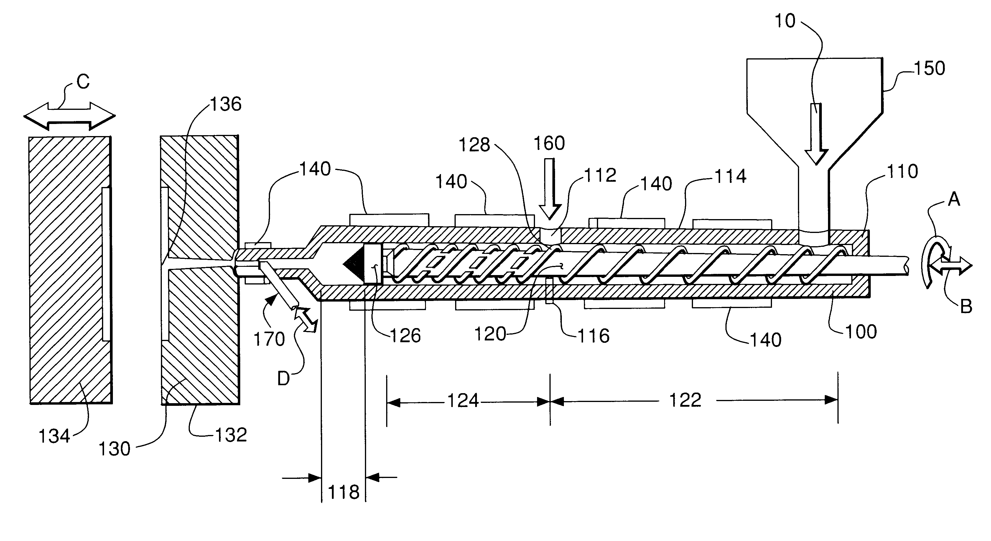
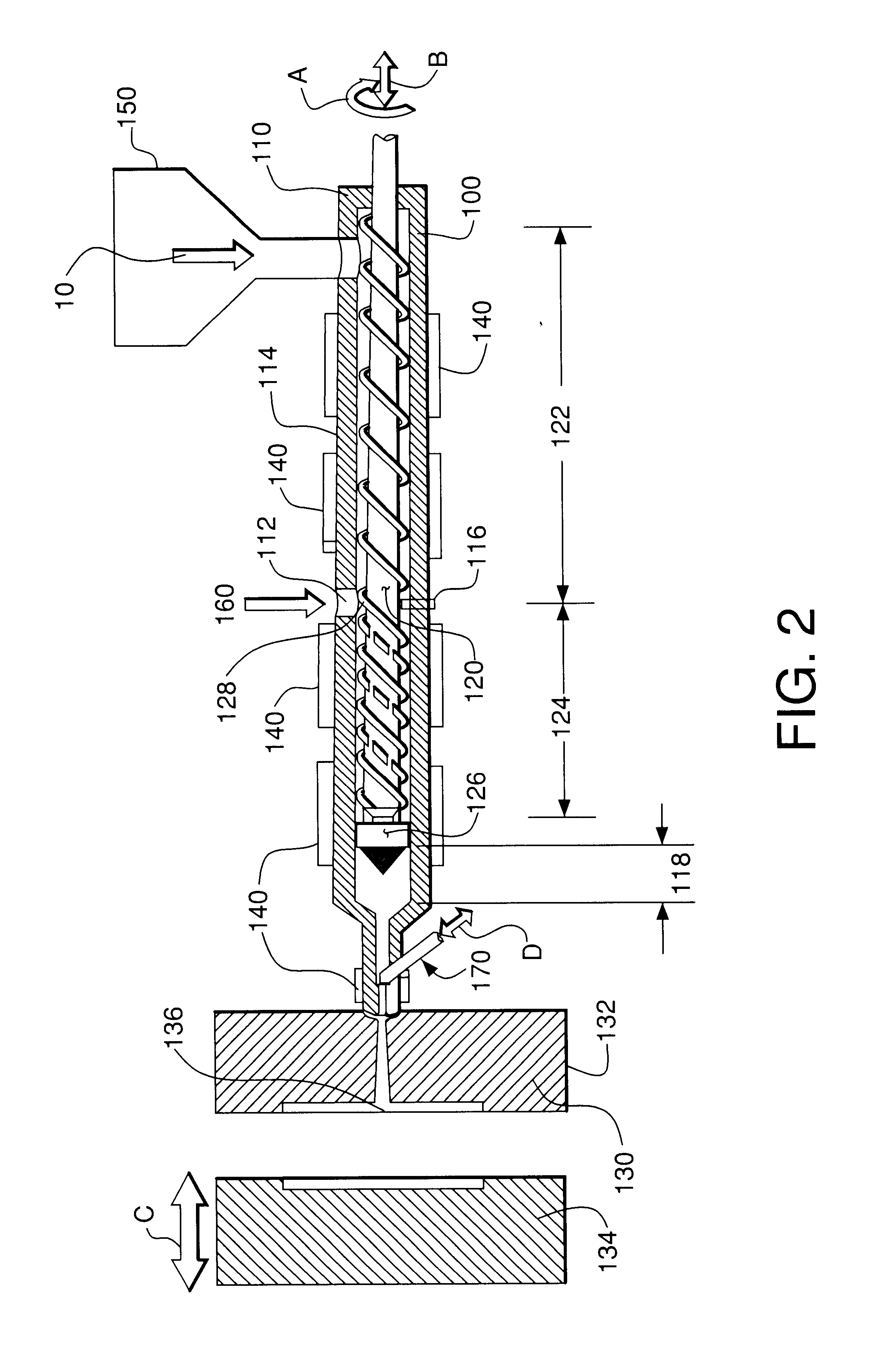
A modified injection molding machine, supplied by Arburg Inc., 125 Rockwell Rd., Newington, Conn. 06131, "Alrounder C500-250 Jubilee" had a capacity to exert a clamping force of 55 metric tonnes. The screw and barrel of the machine were modified in order to form microcellular plastics. A gas injection port was located in the middle section of the barrel through which carbon dioxide at a high pressure was injected into the plasticized metal feedstock as it traveled along the heated barrel. Average barre...
example 2
This example shows that the formation of micropores is not affected by metal alloy chemistry when using the same binder system.
Feedstocks containing alloy powders of three different chemistries (Table A) were procured from Advanced Metalworking Practices (AMP), Inc. (12227 Crestwood Dr., Carmel, Ind. 46033). All of these feedstocks contained a proprietary binder system developed by AMP. The key properties of these feedstocks are shown in Table A. The Blended 4600 Feedstock was produced by mixing carbonyl iron powder (iron powder derived by the carbonyl process), 2% nickel powder and the proprietary binder developed by AMP. The size and the origin of the nickel powder was not disclosed by AMP. The particle size of the carbonyl iron powder ranged between 1 to 7 microns, with the average particle size of about 4 microns. This feedstock was found to contain approximately 10% binder, as determined by the weight difference in as-molded and sintered parts. The formulation sheets from AMP i...
example 3
This example shows that micro-porous metals can be formed using feedstocks that contain different binder systems.
Commercial feedstocks were purchased from a number of suppliers. In addition, one feedstock was custom formulated with a known binder. Since most of the feedstock systems are proprietary, only limited information about the chemistry and composition of the binder systems is supplied by the feedstock producers.
Table C gives some of the key characteristics of the feedstocks and the binders contained therein. Tables D1 an D2 provide the process parameters used with the feedstocks having different binder chemistries.
AMP (Advanced Metalworking Practices, Inc., 12227 Crestwood Dr., Carmel, Ind. 46033) supplied two of the feedstocks used in this study. The Blended 4600 steel feedstock was prepared by blending carbonyl iron powder with 2% nickel powder.
TABLE D1
TABLE D2
The binder was based on thermoplastic wax but its exact chemistry and composition was not disclosed by AMP. The sa...
PUM
| Property | Measurement | Unit |
|---|---|---|
| Size | aaaaa | aaaaa |
| Size | aaaaa | aaaaa |
| Size | aaaaa | aaaaa |
Abstract
Description
Claims
Application Information
 - R&D
- Intellectual Property
- Life Sciences
- Materials
- Tech Scout
- Unparalleled Data Quality
- Higher Quality Content
- 60% Fewer Hallucinations
Browse by: Latest US Patents, China's latest patents, Technical Efficacy Thesaurus, Application Domain, Technology Topic, Popular Technical Reports.
© 2025 PatSnap. All rights reserved.Legal|Privacy policy|Modern Slavery Act Transparency Statement|Sitemap|About US| Contact US: help@patsnap.com


