Control circuit of brush-less motor, control circuit of sensor-less brush-less motor, brush-less motor apparatus, sensor-less brush-less motor apparatus and vacuum pump apparatus

a control circuit and motor technology, applied in the direction of motor/generator/converter stopper, electronic commutator control, motor/generator/converter stopper, etc., can solve the problems of over-exposure of noise, inability to accurately detect the position of the magnetic pole, and enormous loss of time caused by the above-described caus

Inactive Publication Date: 2004-07-06
EDWARDS JAPAN
View PDF10 Cites 36 Cited by
  • Summary
  • Abstract
  • Description
  • Claims
  • Application Information

AI Technical Summary

Problems solved by technology

Further, when the conventional sensor-less brush-less motor is applied to a vacuum pump of a turbo-molecular pump or the like, the following problem is posed.
Particularly, in the case of a turbo-molecular pump, about one minute is required for accelerating the rotational number of the rotor 150 to reach about 20 rotations per second capable of locking the PLL circuit and therefore, loss of time by the above-described cause is enormous.
Further, there is a case in which noise is superposed on voltage of the motor windings in detecting the magnetic pole of the rotor and the positions of the magnetic poles cannot accurately be detected.
Further, in the case in which the rotor of the brush-less motor is axially supported by a magnetic bearing, for example, when the rotor is subjected to direct current braking in starting to thereby set the magnetic poles to predetermined positions, since

Method used


Image

  • Control circuit of brush-less motor, control circuit of sensor-less brush-less motor, brush-less motor apparatus, sensor-less brush-less motor apparatus and vacuum pump apparatus
  • Control circuit of brush-less motor, control circuit of sensor-less brush-less motor, brush-less motor apparatus, sensor-less brush-less motor apparatus and vacuum pump apparatus
  • Control circuit of brush-less motor, control circuit of sensor-less brush-less motor, brush-less motor apparatus, sensor-less brush-less motor apparatus and vacuum pump apparatus

Examples


ninth embodiment

of Ninth Embodiment)

FIG. 25 is a drawing showing a constitution of a control circuit 49 according to the modified example. In the 2-phase mode, the control circuit 49 nullifies only the output of the Lp signal setting circuit 15 and outputs the resistance value signal Rp from the Rp signal setting circuit 14 regardless of the modes and the other circuit constitution is similar to that of the control circuit 47. When the resistance value signal Rp is outputted in the 2-phase mode, the characteristic of the control circuit 47 immediately after starting can be promoted by the following reason.

The direct current cut filter 2 (FIG. 21) is constituted by combining, for example, a high pass filter and an integrator and is normally provided with an integration characteristic. Therefore, a delay is caused in response to an inputted signal and even when the input signal is rapidly changed, the direct current cut filter 2 cannot follow thereto immediately.

Therefore, during a predetermined time...

modified example 2

(Modified Example 2 of Ninth Embodiment)

As has been explained in the modified example 1 of the ninth embodiment, there are eight kinds of switching between the 2-phase mode and the 3-phase mode (FIG. 22). It has been newly found that there is a case in which among the eight kinds, in switching from the 2-phase mode to the 3-phase mode, that is, in the mode switching of and , the magnetic flux predicting signal .phi. outputted from the adder 13 (FIG. 21) becomes unstable.

According to the modified example, in order to promote the stability of the magnetic flux predicting signal .phi., when the mode is switched from the 2-phase mode to the 3-phase mode, small current to a degree of not effecting influence on the torque of the rotor 6 is conducted to the motor windings 7U, 7V and 7W for a predetermined time period (about 1 through 5 seconds).

First, an explanation will be given of operation of the magnetic flux predicting signal .phi. when small current is not conducted to the motor win...

modified example 3

(Modified Example 3 of Ninth Embodiment)

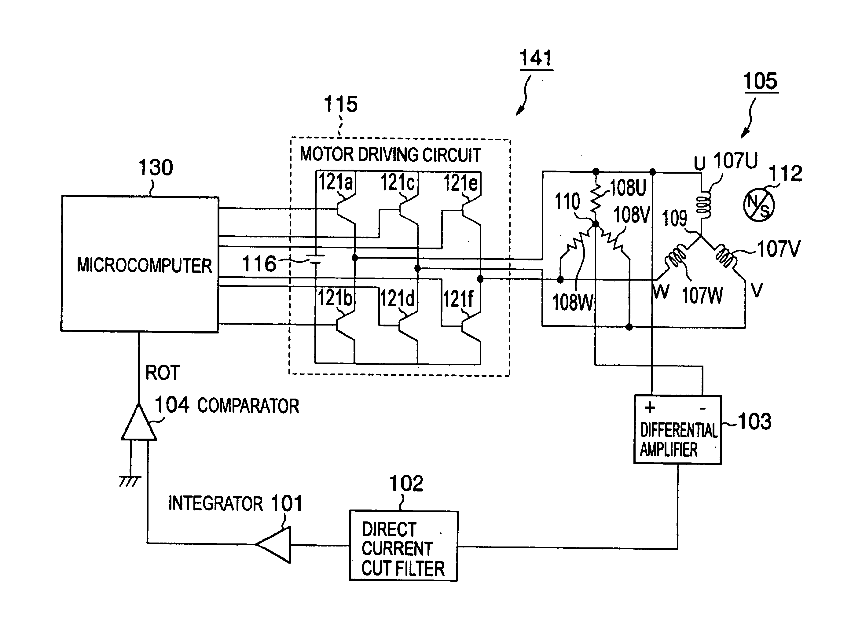
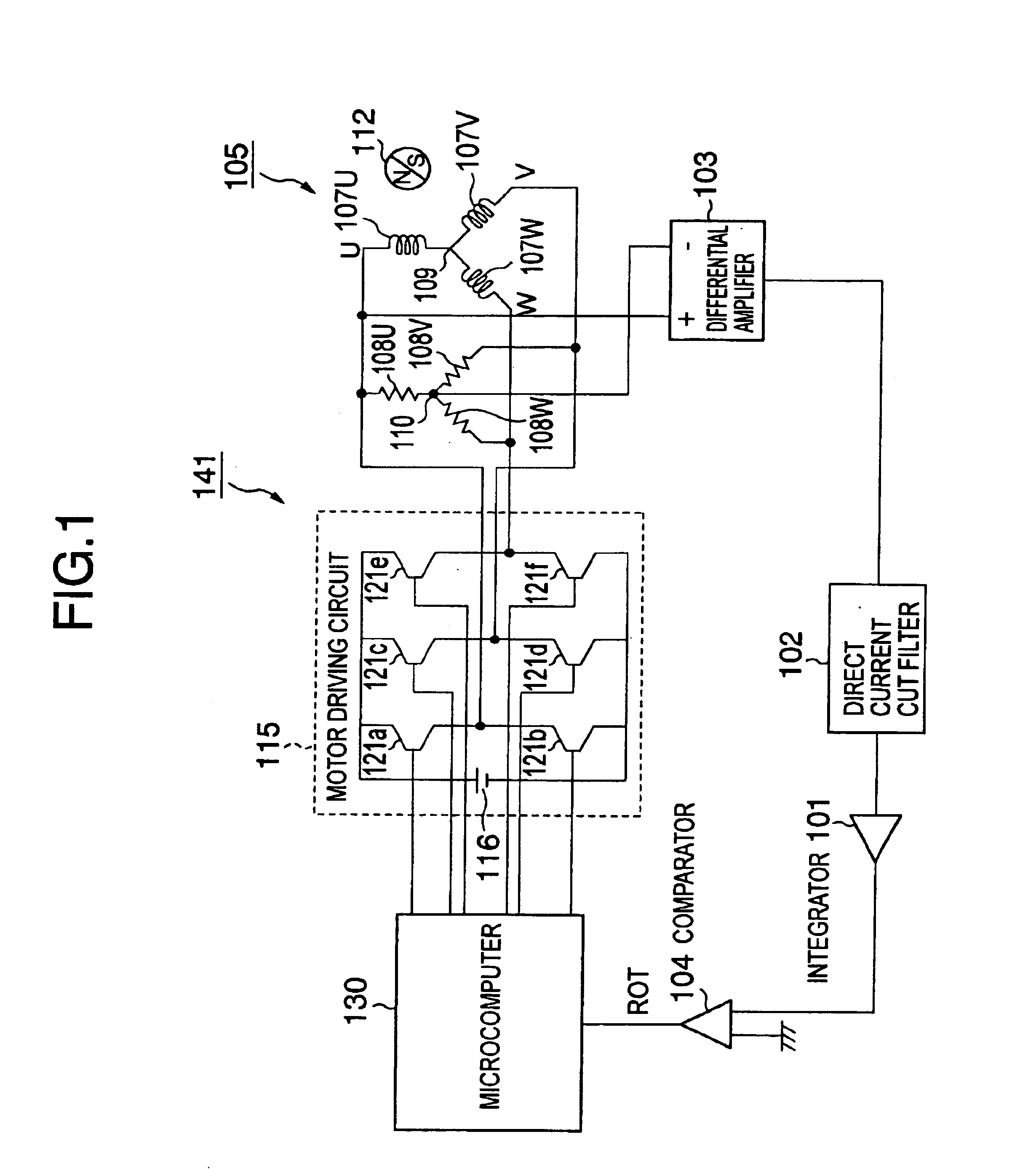
According to the embodiment, the magnetic flux predicting signal .phi. is made to pass the direct current cut filter before inputting to the comparator 4 and the cutoff frequency of the direct current cut filter is switched by whether the rotor shaft 5 is rotated at low speed or at high speed.

As described in the ninth embodiment, there is a case in which in the control circuit 47, even when the output of the Lp signal setting circuit 15 is nullified, the multiplier 12 outputs offset voltage which is not nullified, as a result, the direct current component is superposed on the magnetic flux predicting signal .phi. outputted by the adder 13. Hence, by inserting the direct current cut filter between the adder 13 and the comparator 4, the direct current component superposed on the magnetic flux predicting signal .phi. can be removed.

Meanwhile, since the control circuit 47 controls the motor 5 by the feedback control by the magnetic flux predicting...


PUM


Abstract

To provide a control circuit or the like of a brush-less motor capable of properly controlling current of motor windings by detecting positions of magnetic poles of a rotor at a rotational frequency of the rotor from low rotation which cannot lock a PLL circuit to steady-state rotation for rotating at high speed. Positions of magnetic poles are detected by a change in a magnetic flux (magnetic flux signal) of motor windings caused by rotating a rotor having the magnetic poles, thereby, a synchronizing signal (ROT signal) in synchronism with rotation of the rotor is generated. When the rotor is rotated at a low rotational frequency which cannot lock a PLL circuit, the rotor is driven by using predetermined two driving voltage vectors among outputable driving voltage vectors and when a rotational frequency capable of locking the PLL circuit is reached, the rotor is driven by successively outputting the outputable driving voltage vectors in synchronism with the positions of the magnetic poles detecting the outputable driving voltage vectors. Further, the magnetic flux signal is provided by using voltage between two phases at which phases and magnitudes of voltage drop caused by inductances of motor windings are equal to each other.

Description

1. Field of the InventionThe present invention relates to a brush-less motor, a control circuit thereof and the like, relates to a constitution used in a vacuum pump of, for example, a vacuum pump of a magnetic bearing type turbo-molecular pump or the like or a magnetic bearing spindle or the like.2. Description of the Related ArtConventionally, starting a brush-less motor is carried out as follows.There is a brush-less motor having a rotor having a permanent magnet of two poles and three motor phase windings for generating a magnetic field for rotating the rotor at its surrounding.In such a brush-less motor, there is a constitution in which as a sensor-less brush-less motor control circuit which is not provided with a sensor for detecting positions of magnetic poles, current for driving the motor is made to flow to two motor windings in three motor windings to thereby rotate a rotor, by rotating the rotor, positions of magnetic poles of the rotor are detected from induced electromo...

Claims


Application Information

Patent Timeline
IPC IPC(8): H02P6/00H02P6/14H02P6/20H02P6/06H02P6/08H02P6/16H02P6/28
CPCH02P6/14H02P6/20H02P6/18
Inventor KAWASHIMA, TOSHIAKI
Owner EDWARDS JAPAN
Why Eureka
Try Eureka