
One piece sleeve gas manifold for cell stack assemblies such as fuel cells

a fuel cell and assembly technology, applied in the direction of cell components, lighting and heating apparatus, separation processes, etc., can solve the problems of similar manifold and restraint, fuel cell stack electrolytes with proton exchange membrane electrolytes, and the plate itself is much more expensive than the plate, so as to reduce the cost, reduce the leakage, and simplify the assembly

Inactive Publication Date: 2004-07-20
INT FUEL CELLS
View PDF3 Cites 31 Cited by
  • Summary
  • Abstract
  • Description
  • Claims
  • Application Information

AI Technical Summary

Benefits of technology

Objects of the invention include improvements in supplying fluids to, containing fluids in, and removing fluids from a plurality of cells assembled into a stack, such as fuel cells, electrochemical cells, and enthalpy exchange devices. Other objects of the invention include: reduction of leakage, simplification of assembly, and reduction of costs in such cell stack assemblies; improved cell stack gas manifolds; and improved manifold seals and constraint.

Problems solved by technology

This renders the plates themselves much more expensive than plates which are fabricated for use with external manifolds.
However, fuel cell stacks with proton exchange membrane electrolytes, as in U.S. Pat. No. 6,024,848, have similar manifold and restraint problems.
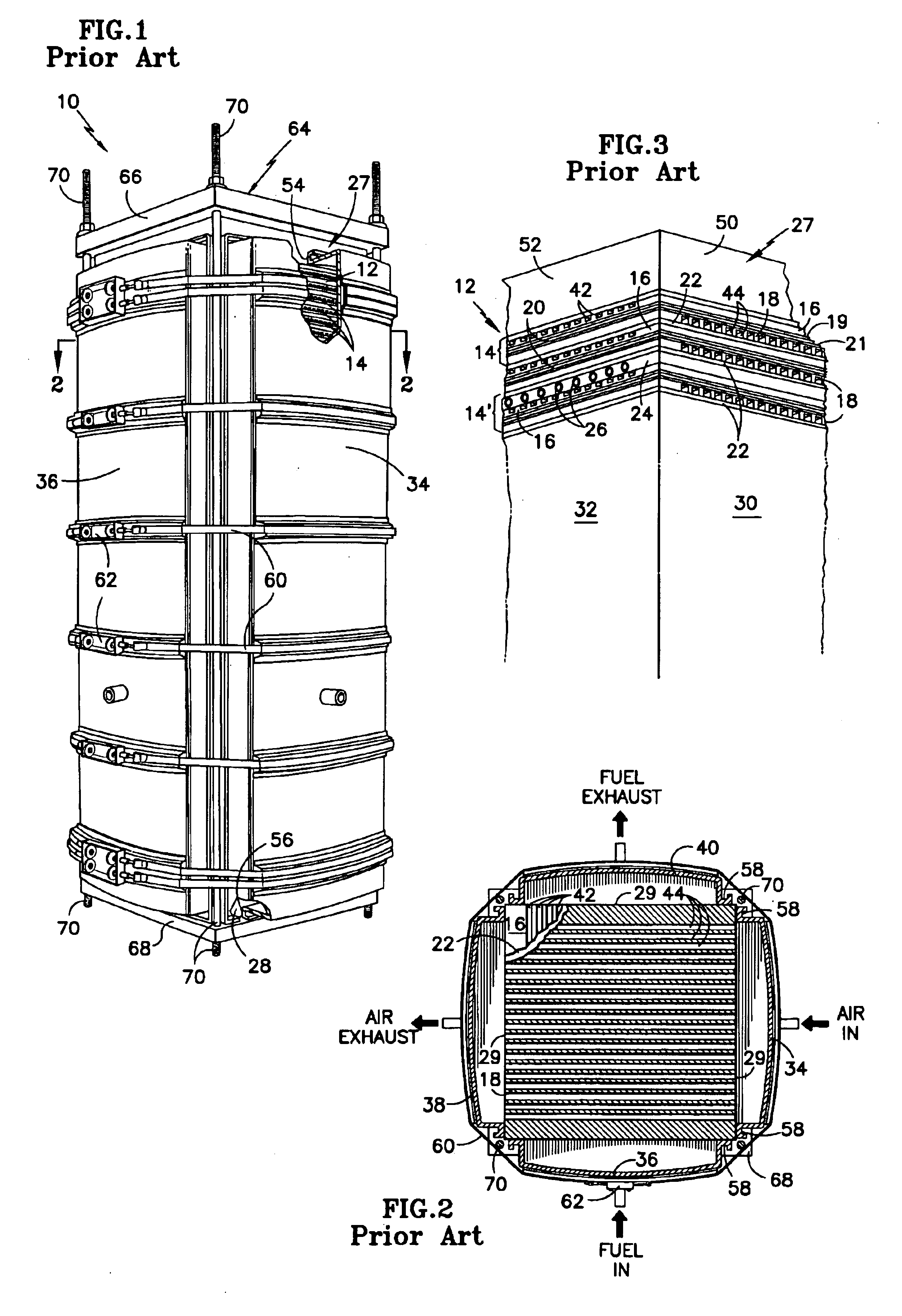
The external manifold system described with respect to FIGS. 1-3 presents difficulty in assuring the lack of leakage to the external environment, is comprised of many extensive components, and assembly thereof is extremely expensive.
The leakage of fuels, such as hydrogen, in prior art fuel cell stack assembly designs may be too great for use in vehicles and residential applications.

Method used


Image

  • One piece sleeve gas manifold for cell stack assemblies such as fuel cells
  • One piece sleeve gas manifold for cell stack assemblies such as fuel cells
  • One piece sleeve gas manifold for cell stack assemblies such as fuel cells

Examples


Embodiment Construction

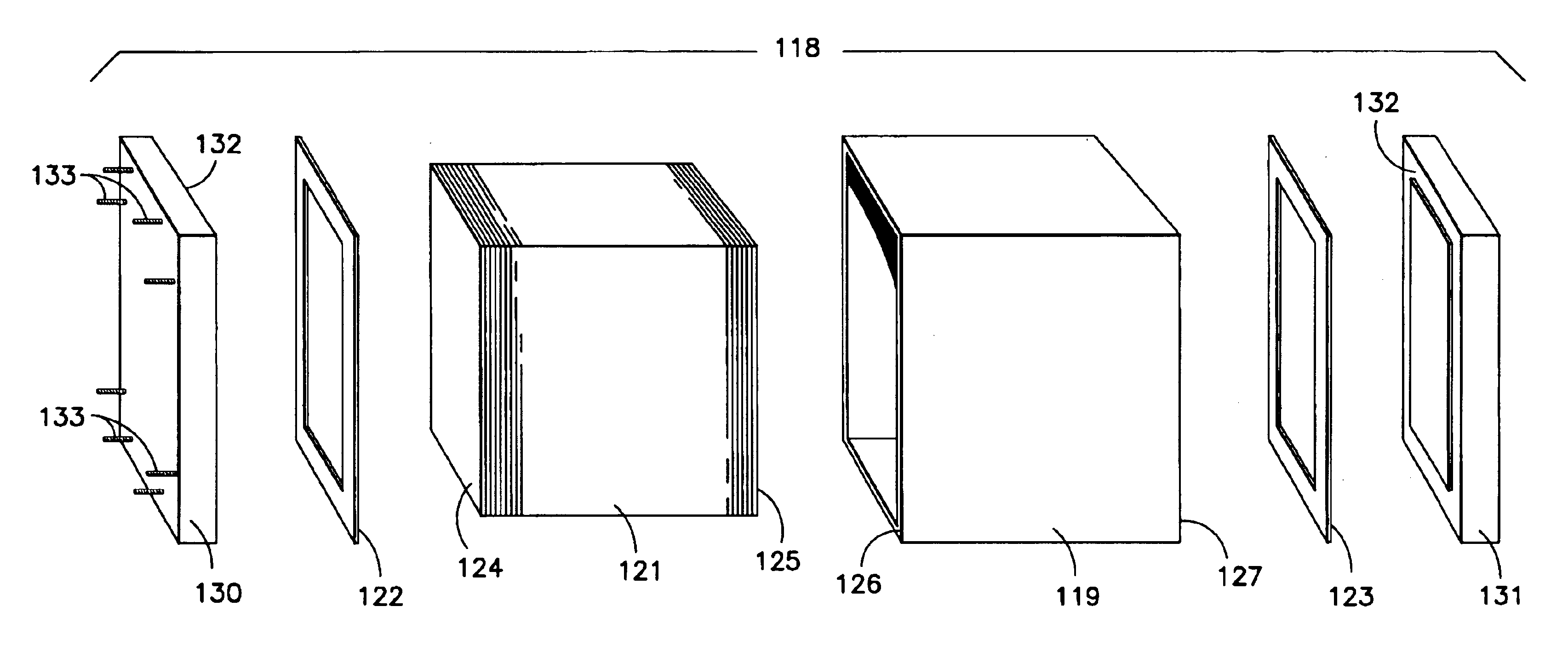
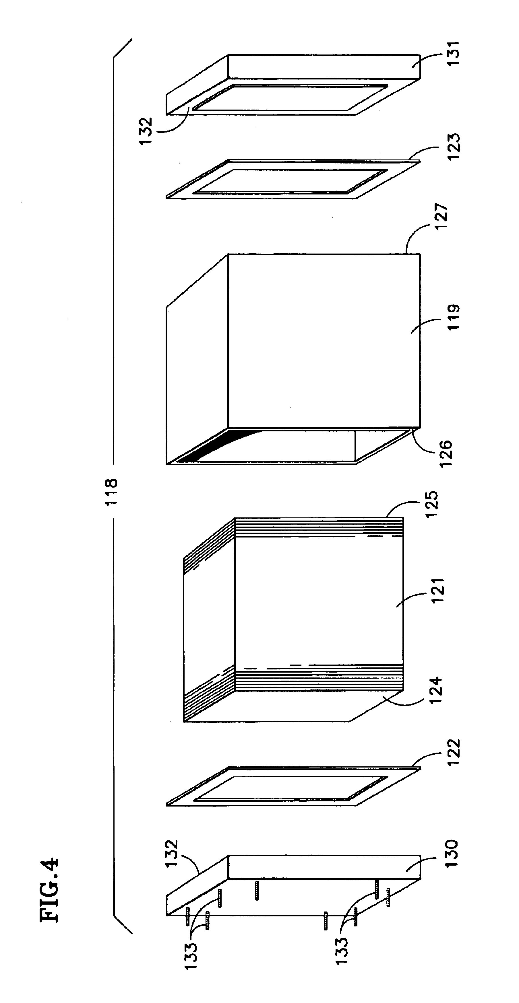
Referring to FIG. 4, in a system 118 employing fluids, a sleeve manifold 119 according to the invention is adapted to have a stack of cells (of a fuel cell system or electrochemical cell system) 121 inserted therein after which seals or gaskets 122, 123 will be applied to end pieces 124, 125 (such current collecting blocks) of the cell stack 121 and to the end edges 126, 127 of the sleeve manifold 119. Pressure plates (or end plates) 130 and 131 each have a land 132 to receive a respective gasket 122, 123 and the whole assembly 118 will be compressed and then held by tie rods 133 (shown only at the left end) extending outside the sleeve manifold 119, through and between the end plates 130, 131 and secured by nuts (not shown), as is known in the art and shown in FIG. 1. In FIG. 4, the simplified showing of the sleeve manifold 119 is of a hollow rectangular prism, and does not illustrate any manifold chambers, for simplicity. The seals or gaskets may be of an expandable elastomer as d...


PUM

PropertyMeasurementUnit
heightaaaaaaaaaa
heightaaaaaaaaaa
heightaaaaaaaaaa

Abstract

A stack of plates (121) (such as fuel cells, electrochemical cells, or enthalpy exchange plates) is surrounded by a sleeve manifold (119) which is shaped to provide manifold chambers (34-39; 146-149; 151-153; 156-158; 161-163; 180-187), and including surfaces (142) for seals (143) to isolate the manifold chambers from each other. Sleeve manifolds (119a, 119b, 119c) may be formed of material of varying thickness, by machining, casting, or extrusion, or may be formed of material (119d) of uniform thickness by bending, casting or extrusion. Sleeve manifolds may be formed of metal, graphite, plastic or reinforced plastic.

Description

This invention relates to a single-piece sleeve manifold which will supply, contain and remove fluids, including fuel reactant gases, oxidant reactant gases, and cooling fluids, in fuel cell stack assemblies, electrochemical cell stack assemblies, and including exchange gases in enthalpy exchange devices.In cell stack assemblies, it is known to use internal reactant and coolant manifolds as well as external coolant and reactant manifolds. Internal manifolds generally comprise passageways made within the various plates that constitute the cells of the cell stack assemblies. This renders the plates themselves much more expensive than plates which are fabricated for use with external manifolds. Internal manifolds have potential leakage paths between the plates of every cell, the leakage thereby being to the external environment. While external manifolds may also leak gases to the external environment, the avoidance of such leaks is more easily accomplished. Internal manifolds are gener...

Claims


Application Information

Patent Timeline
Patent Type & Authority Patents(United States)
IPC IPC(8): B01D53/22C25B9/00F28F3/08F28F3/10H01M8/02H01M8/24H01M8/04H01MH01M8/10
CPCH01M8/0271H01M8/248H01M8/2485Y02E60/50H01M8/2484
Inventor GRASSO, ALBERT P.JOHNSON, HENRY G.
Owner INT FUEL CELLS
Learn More