Joint structure of coolant passage, tube seal, and gas turbine

a joint structure and coolant passage technology, applied in the field of gas turbines, can solve the problems of small steam leakage, difficult to increase the machining accuracy of the face, and decrease the work that can be taken out of the turbin

Inactive Publication Date: 2004-08-03
MITSUBISHI HITACHIPOWER SYST LTD
View PDF10 Cites 5 Cited by
  • Summary
  • Abstract
  • Description
  • Claims
  • Application Information

AI Technical Summary

Benefits of technology

In this gas turbine, the rotor disk and the dynamic blade are coupled by the joint structure of the cooling flow passage, to supply and recover the coolant to and from the dynamic blade. The dynamic blade and the rotor disk of the gas turbine reach high temperatures, and are exposed to a high centrifugal force, and hence the dynamic blade and the rotor disk may be shifted from each other due to thermal deformation, and a large force acts on the sealing structure. Since the joint structure applied to this gas turbine seals the coolant passage by bringing the tube seal, whose end being formed into a spherical shape, into line contact with the inner surface of the coolant passage, even if a high centrifugal force acts thereon, the sealing effect can be maintained. Further, even if the dynamic blade is shifted, the tube seal exhibits the sealing effect, while being inclined by the spherical end and the elastic member provided on the barrel of the tube seal, to absorb the shift. In this manner, even under high temperatures and under an environment where a high centrifugal force is acting, wastage of the coolant can be made as small as possible by the stable sealing effect, and the thermal efficiency of the gas turbine can be improved.

Problems solved by technology

However, if this compressed air is used for cooling, the work that can be taken out from the turbine decreases.
However, it is difficult to increase the machining accuracy of the face, and steam leaks slightly from this portion.
Therefore, a gap is always formed at the seal point 125, causing a problem in that steam leaks from this gap.
However, when a movement in the direction perpendicular to this radial direction occurs, if the movement is very small, this joint structure can correspond thereto, but if the movement is large, a gap is formed between the flange and the root of the dynamic blade, and hence causing a problem in that steam leaks from this gap.
However, when the shift of the dynamic blade is large, the inclination of the tube seal increases, to cause leakage of the coolant in the end where the working face is formed.

Method used


Image

  • Joint structure of coolant passage, tube seal, and gas turbine
  • Joint structure of coolant passage, tube seal, and gas turbine
  • Joint structure of coolant passage, tube seal, and gas turbine

Examples


first embodiment

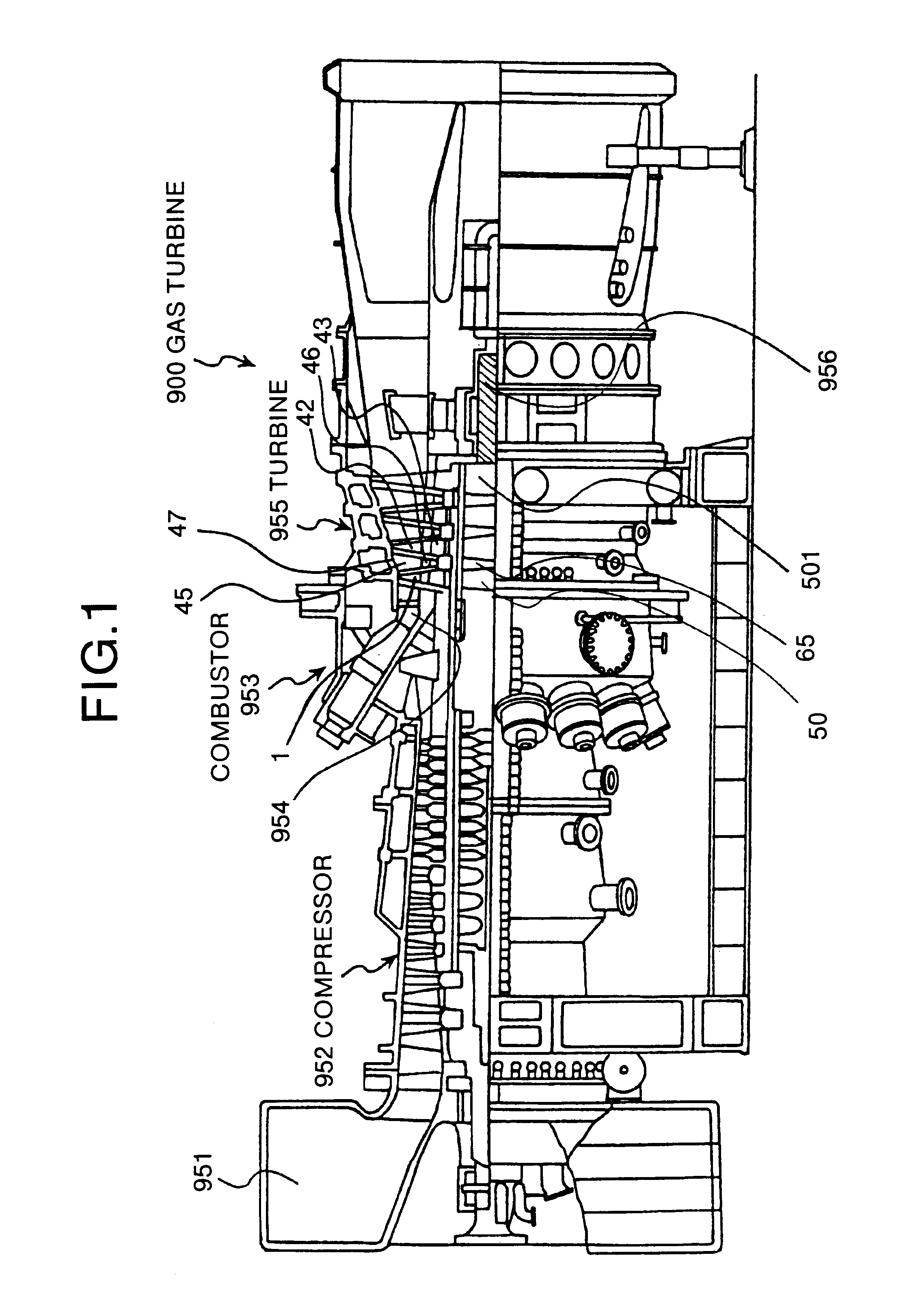
FIG. 1 is an explanatory diagram which shows a gas turbine according to this invention. The gas turbine 900 cools high-temperature members in the gas turbine, such as a dynamic blade, a rotor desk or a stationary blade, by steam. The air taken in from an air intake 951 is compressed by a compressor 952, to become high-temperature and high-pressure compressed air, and is fed to a combustor 953. In the combustor 953, a gas fuel such as a natural gas or a liquid fuel such as light fuel oil or light heavy fuel oil is supplied to the compressed air to burn the fuel, to thereby generate a high-temperature and high-pressure combustion gas. This high-temperature and high-pressure combustion gas is guided to a tail pipe 954 of the combustor, and injected to a turbine 955.

The stationary blade and the dynamic blade of the turbine 955 are cooled by steam. The steam that cools the dynamic blade 1 is supplied through a steam supply flow passage (not shown) provided in a main spindle 956 of the tu...

second embodiment

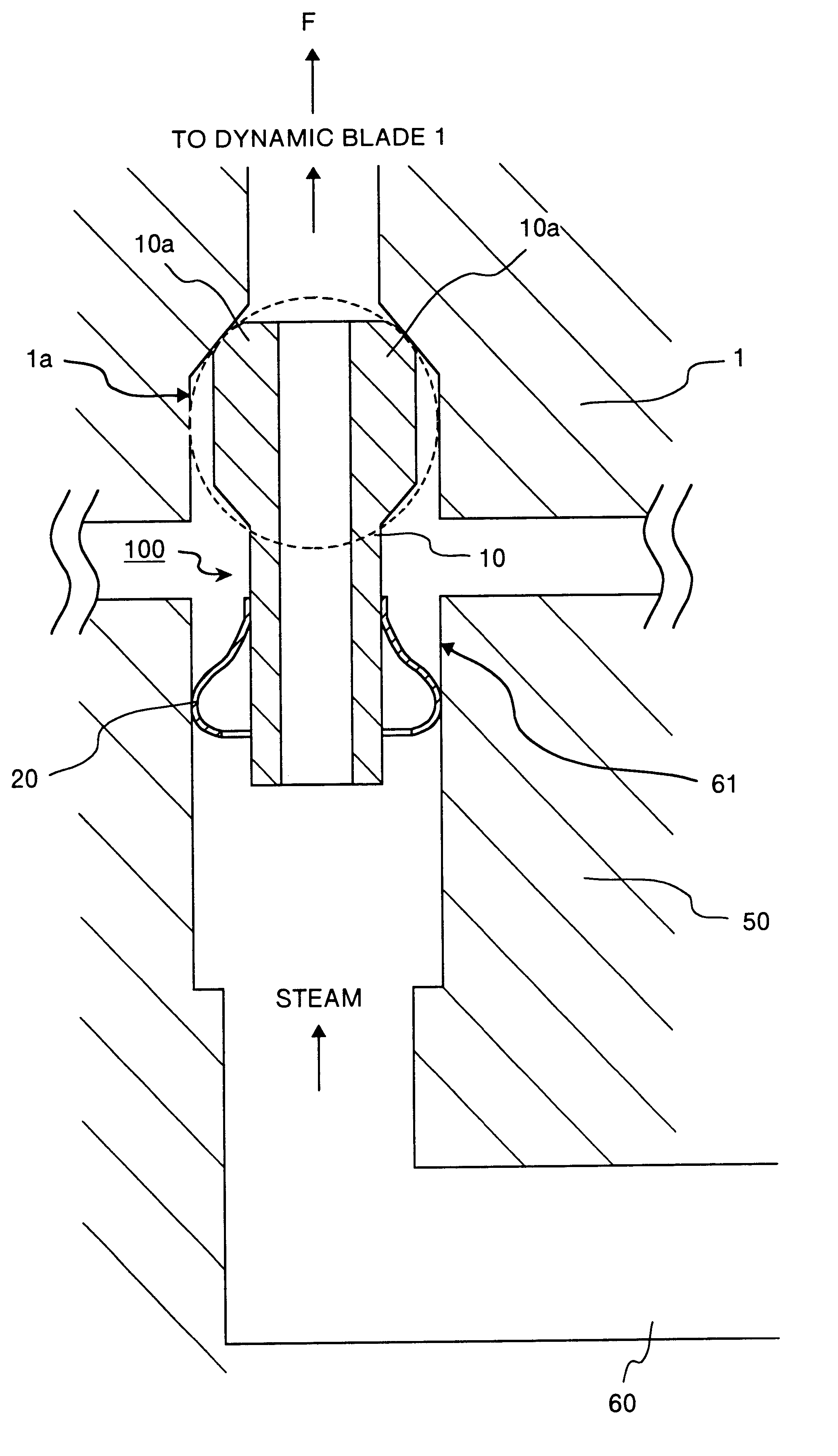
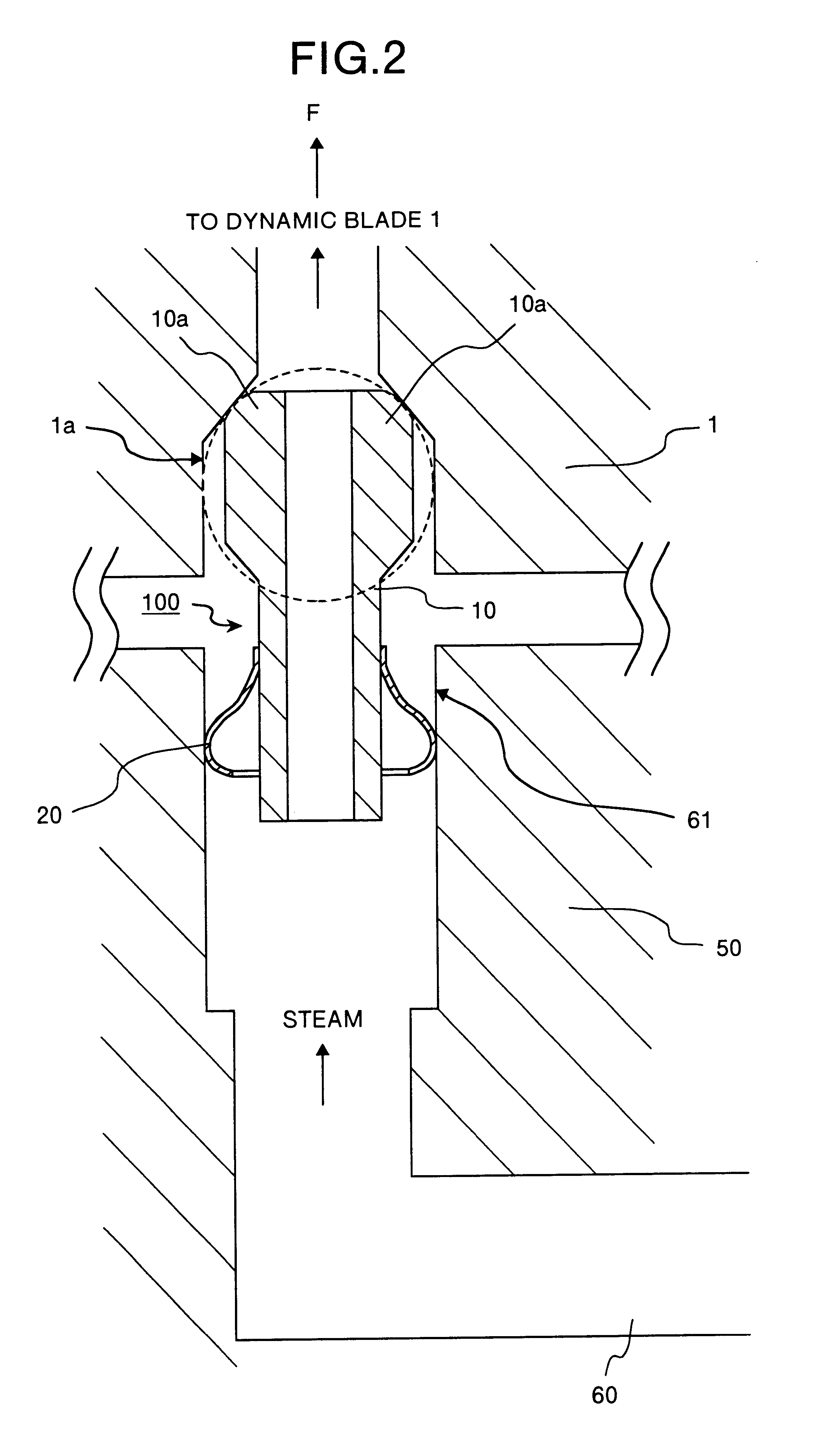
FIG. 5 is a cross section which shows a joint structure of a cooling passage, which supplies cooling steam from the rotor disk side to the dynamic blade side or recovers it from the dynamic blade side to the rotor disk side, according to this invention. This joint structure is applicable when the shift between the dynamic blade 1 and the rotor disk 50 is small. When the dynamic blade 1 is shifted, a protruding portion 32 provided in a barrel 12 of a tube seal 101 abuts against an opening end 61a of a steam supply pipe outlet 61 provided in the rotor disk 50, to restrict this shift.

In this joint structure, a tube seal 104 having a tubular barrel 12 is used, and a curved surface is provided on the outer periphery of an end 12a of the barrel 12, so that this curved surface abuts against the internal surface of a steam supply port 1a in the dynamic blade 1. A protruding portion 32 which restricts a radial movement of the tube seal 104 is fitted on the side of the barrel 12 and at a posi...


PUM


Abstract

A tube seal is fitted with a spherical spring, being an elastic member, at one end of a tubular barrel. The end where the spring is fitted to the tubular barrel is inserted into a steam supply pipe outlet, which is a coolant passage provided in a rotor disk. The other end of the barrel is formed into a spherical shape, and this end is inserted into a steam supply port in a dynamic blade, being another coolant passage port, and abuts against the internal surface of the steam supply port.

Description

1) Field of the InventionThis invention relates to a gas turbine which uses a coolant such as air and steam for cooling a dynamic blade. More specifically, this invention relates to a joint structure of a coolant flow passage in the gas turbine for coupling a flow passage for supplying a coolant from a rotor disk to the dynamic blade, a tube seal and the gas turbine.2) Description of the Related ArtIn order to increase thermal efficiency in the gas turbine, a technique in which steam is used as a coolant instead of the air, to cool hot members such as a dynamic blade, a rotor disk or a stationary blade of the gas turbine is now being used. This is due to the following reasons. That is, the specific heat at constant pressure of dry steam is cp=1.86 kJ / kgK under a standard condition, which is a value almost twice as large as the specific heat at constant pressure of the air, cp=1.00 kJ / kgK. Therefore, the steam has a large heat capacity as compared with the air of the same mass, and t...

Claims


Application Information

Patent Timeline
Patent Type & Authority Patents(United States)
IPC IPC(8): F01D5/02F01D5/08F01D5/18F01D9/06F01D25/00F02C7/18F16L27/04F16L37/02
CPCF01D5/081F01D9/06F16L27/04F16L37/025F05D2260/2322
Inventor UEMATSU, KAZUOOHYA, TAKEAKI
Owner MITSUBISHI HITACHIPOWER SYST LTD
Why Eureka
Try Eureka